3MP Flatfoto Digital Camera for Aerial Photography from RC Aircraft
I bought a Flatfoto 3 MP digital camera at Radio Shack a few months ago and finally got around to opening it up and modifying it for aerial photos. It lends itself very well for AP. It is very light, inexpensive, takes SD memory cards, will accept 5V from the receiver, and has the same voltage logic as the Aiptek Pencams. This last item means that Mr.RC-Cam's CamMan PIC will work with no changes. Please read his CamMan page for full details on how the PIC functions: http://www.rc-cam.com/project1.htm
Radio Shack has stopped selling these, but they can be had on eBay for around $30. http://search.ebay.com//search/search.dll?from=R40&satitle=flatfoto+3 You will also need to buy an SD memory card. The modifications to use this camera for AP are detailed here and in the pictures. All pictures are thumbnails, so click on them to see the full size image.
|
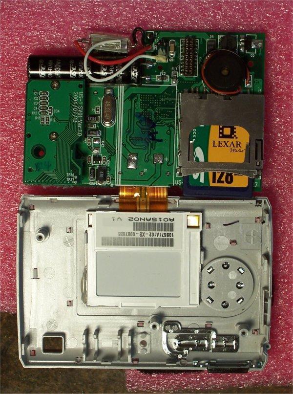
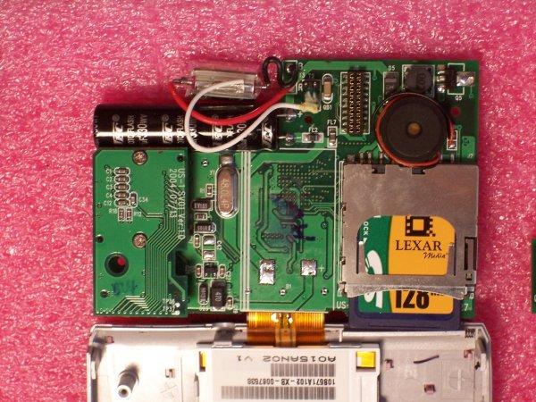
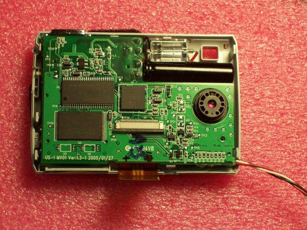
DO NOT TOUCH the flash capacitor leads. Be very careful not to touch them - ask me how I know... 1. Take the front of the case off. You will need a small Phillips head screwdriver to remove the five screws holding the front of the case on. Once you have the front of the case off, you need to take out the internal boards. All the internal boards are attached to the back of the case. To remove those board, you must take out three screws. With those screws removed, you can unfold the main board. If you want to avoid any possible damage to the LCD screen ribbon cable, disconnect the ribbon cable before you unfold it. See next step. |
|
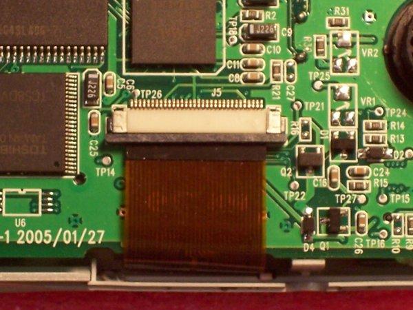
2. The main board is attached to the LCD screen, so carefully remove the ribbon cable to LCD screen from the main board by sliding the connector apart and pulling the ribbon cable out. Carefully take out the main board, and don't lose the plastic button insert on the side or any of the screws you have removed. You will do the same steps in reverse to put everything back together. |
3. Carefully unfold the internal lipo battery and desolder the two connectors. The board was marked + on mine to show polarity; take note on yours if that mark is not there. Go ahead and remove it at this time to make sure you don't fry anything during the modifications. Here is your first choice in setup. Do you want to power the camera from an external source or use the internal battery? This battery has a small capacity and will run out of charge pretty quickly.
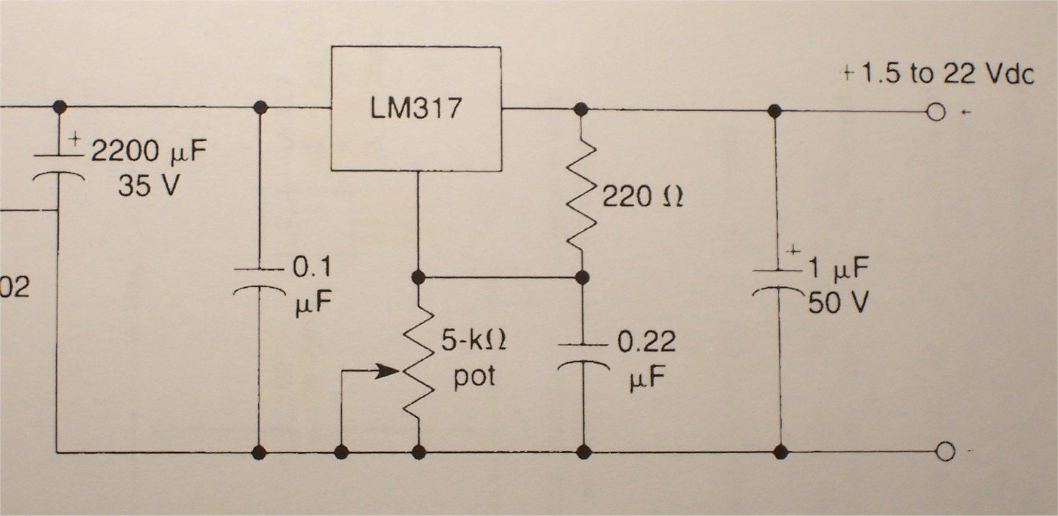
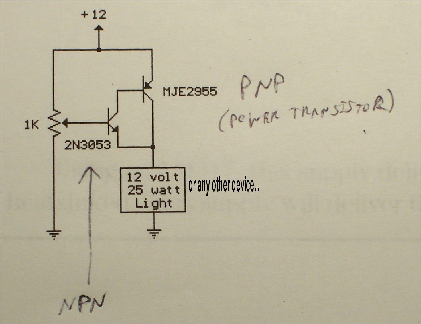
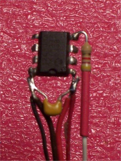
My preferred method is an external power source, so I needed to determine the voltages that would work if I removed the battery completely and went with an external power source. I wanted to use either the 5 volts coming from the receiver or a different source such as the main motor battery. The lipo has a nominal charge between 3.7 and 4.2 volts, so I started at 4 volts. I tried two voltage regulators (shown: LM317 based and PNP-NPN transisitor based), but neither of them kept the camera happy at 4 volts. Using the potentiometer adjustments, I slowly turned the output voltage up to where the camera worked and stayed on when powered by an external battery. It turns out the camera works fine at 5 volt input right to the battery connectors on the main board. You must run the external power right to the battery connectors on the main board. If you run 5 volts to the USB port power connections, the camera goes into charge mode or tries to act like an external storage device to a computer, and will not take pictures. If you remove the battery, you now have a tiny (~100-200mah ?) lipo as a bonus, and you will have room to put the CamMan PIC inside the camera.
|
|
I took the battery out of mine and it works fine, but if you do want to keep the battery installed, you can reinstall it after you have everything else in place. You should take it out now so you don't short circuit something with power applied. If you leave the battery installed in your final setup, the +5 volts from the receiver will not go the camera, but ground must be common to all components, so ground will run to both the CamMan PIC and camera.
Did I mention not to touch the flash capacitor leads? Don't give in to that urge.
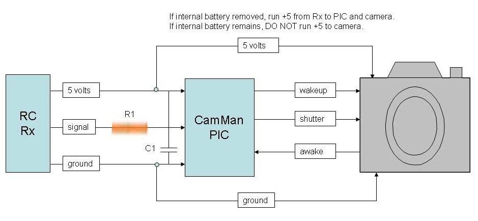
4. You must now locate the 3 contact points in the camera that will run from the camera to the CamMan PIC. They are "wakeup", "shutter", and "awake". The CamMan PIC monitors the RC signal coming from the RC receiver. When it goes from low (1 ms PWM) to high (2 ms PWM), it begins the "take picture" process. It first checks the "awake" line coming from the camera. If the line is high, it decides that the camera is awake. If that "awake" line is low, it momentarily drives the "wakeup" output to ground. This turns the camera on.| Side Note: Some digital cams don't use this same voltage logic to wake up. Some "power on" switches in cameras actually connect to the high voltage (Vcc) of a camera (3 to 5 volts). Since the the Flatfoto uses the same voltage logic as the Aiptek cameras, which the CamMan was designed for, we are in luck and will not have to invert this logic. The FlatFoto is based on the Smal digital camera chipset http://www.smalcamera.com/up5lcd.html , the same chipset in one-time-use digital cameras like the Ritz Dakota. Interestingly, the Dakota does use an active high wakeup voltage logic, so if you ever try to solder a CamMan into a Dakota, you have to invert the wakeup signal from 0 to 5 volts using a couple transistors. The Argus also uses the same logic as the Dakota. Please see my Dakota webpage and Argus webpage for all the details on this. |
Now that the camera is awake, the last step in the process is to trip the shutter. The CamMan PIC drives the "shutter" output to ground momentarily. The camera stores the picture and is ready for the next shot. If you take another shot within 1 minute, the camera will still be awake and the CamMan won't have to wake it up. Otherwise, it goes through the wakeup/power-on process again. The LCD screen comes on automatically during the power-on cycle.
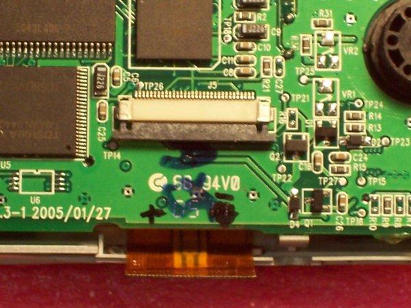
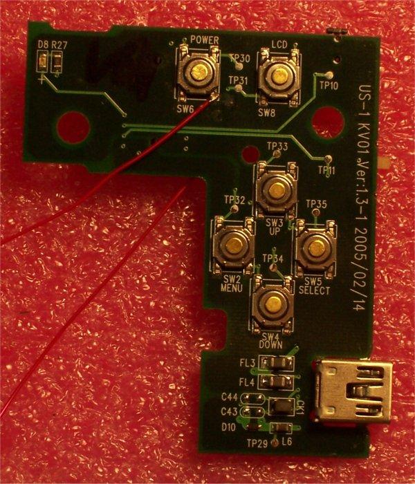
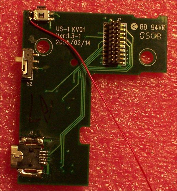
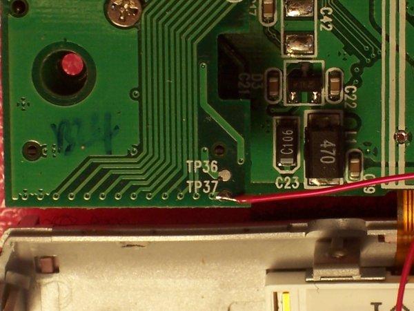
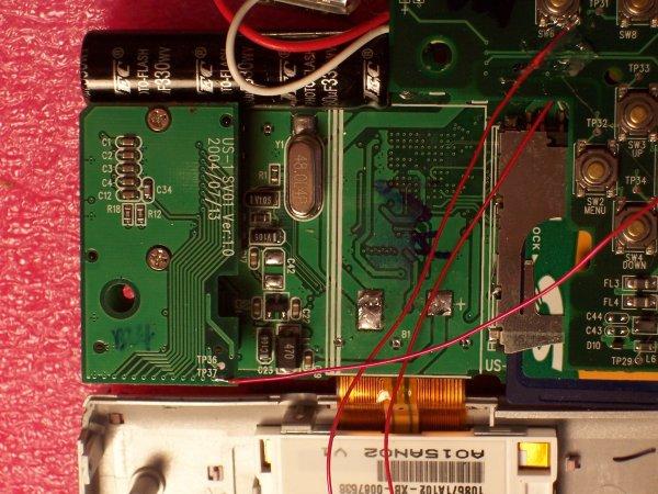
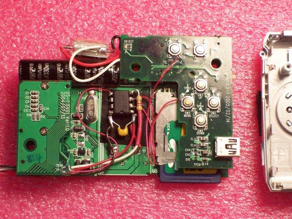
These "wakeup", "shutter", and "awake" spots in the camera are shown in these pictures. The "wakeup" line is attached to the camera's power switch. The "shutter" line is attached the camera's shutter button. The "awake" line is attached to TP37 on the daughterboard on the left side of the camera. When the camera is on, that pin is at 3.8 volts. When the camera is off, that pin is at 0 volts.
|
|
|
|
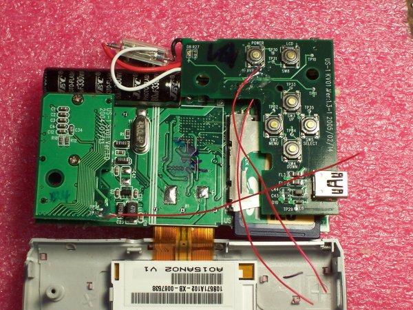
5. You must run all the lines from the CamMan PIC to the camera. With the battery removed, there are 5 lines: +5, GND, SHUTTER, AWAKE, WAKEUP. With the battery installed, there are 4 lines: GND, SHUTTER, AWAKE, WAKUP. If you took the battery out, you now have a place to put the PIC. If you leave the battery installed, the PIC will have to be installed externally to the camera case, since there is no other empty space in the camera. These pictures shows the connections that must be made to get this whole thing working. You must also run three lines from the receiver to the CamMan PIC. They are the power lines (+5, GND), and the RC signal line. Make sure to put the 0.1MF capacitor (C1) across the power lines at the PIC, and to put the 4.7K resistor (R1) in series with the RC signal line.
|
|
|
With the internal battery removed, you won't be able to use the FlatFoto without an external power source, but you also won't be running out of juice while airborne. Perhaps the best answer is a small lipo charger circuit that you could put in-line with the internal lipo batter, but I didn't go that path. If you decide to try that, please post your circuit and setup at RCGroups so we can all try it. A simple 4 volt regulated source in line with the battery might also work, but I tried to keep this as simple as possible.
|
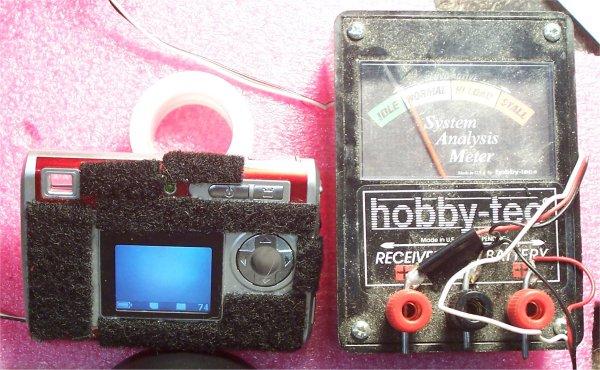
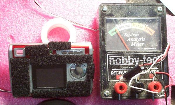
6. Your second choice in this setup involves the LCD screen. You would think that the LCD would draw a lot of current, so you would want to leave it unattached. However, my testing with a servo current ammeter showed that the screen does not draw very much current. The current draw was just slightly higher with the LCD attached. The top image shows the current draw with the screen on, and the bottom image shows the current draw with the screen off. The biggest current draw occurs during the recharge of the flash capacitor. Since you will be using this in the daytime, the flash won't fire and the capacitor won't have to recharge. |
If you do want to disconnect the LCD, the camera works fine without it. When pictures are taken, the camera makes a different sound than when the LCD is attached, but the pictures are still stored to the SD card. I left the LCD screen on my camera attached; I won't be using it in flight obviously, but it can be used to review pics and to navigate the menus. The LCD can also be turned off manually using the LCD button, but will come back on if it goes through the sleep-wake cycle. The CamMan PIC takes care of waking the camera up if it goes to sleep, but as I said earlier, the LCD will come back on when it wakes up.
7. If you are powering the camera from the receiver, when you apply power to the receiver, 5 volts will run to the camera and PIC. If your receiver can handle 6 volts and you use that, you may have to reduce the voltage going to the camera with a couple diodes, a low-voltage drop 5 volt regulator, or a transitor based voltage regulator like I used originally to get the voltage down to 4 volts. A standard LM7805 will not work reliably with a drop from only 6 volts to 5 volts. 7805's need at least 7 volts input to function reliably. I have not tried powering the camera with 6 volts, as it may not like voltage that high.
|
8. Before you put the front of the case back on, adjust the focus. It is
much easier to do this with the front of the case off. After you have it focused, put some
type of plastic glue locktite to keep it locked. 9. The camera can be turned on manually or via the wakeup function of the CamMan. Pulse your input channel from low to high and back to activate the CamMan, then pulse it again to trigger the shutter. The first time you turn it on, do it manually with the button on the camera. The flash capacitor will charge and that takes a lot of current. Sometimes the momentary pulse from the CamMan PIC is not long enough to get the capacitor charged the first time. After that first time, the cap is charged and the wakeup pulse works fine. Good luck with the camera and post your pics! |