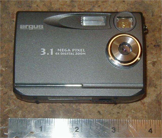
The Argus 3.1 MegaPixel digital camera has lousy optics; it's 3.1 million pixels does not produce a great picture and you can probably get close results with an Aiptek 1.3 Pencam. Why bother with it? It has an NTSC baseband video out, so it can be used to take still digital pics while at the same time the video output can be sent to an RF transmitter and the real-time video can be viewed on the ground. It takes standard SD memory cards, so the same card I use in my Aiptek SD can be used in this camera, and it records video at 30 fps with pretty good quality. I found my Argus 3.1 at CompUSA in the manager's specials for $50. If you can find a similar deal, buy it and see what you can accomplish.
|
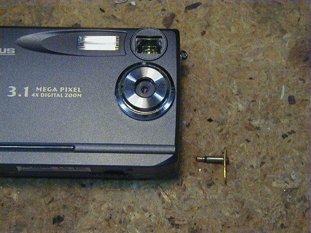
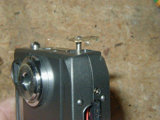
If you want to use the video out feature, plug in the mini-plug to turn off the LCD screen on the back of the camera and pipe the video signal to a transmitter. A neat feature here is that a metal dummy plug (it must conduct electricity) also turns off the LCD screen, saving battery life. Here you can see the dummy connector I made and where it fits into the side of the camera. It has a brass handle soldered to the end so it can be pulled out. Get it the right length so that when it closes the circuit that disables the LCD screen, it fits into the camera perfectly with no extra length. |
|
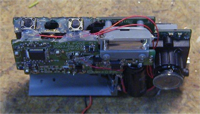
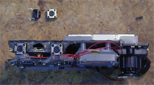
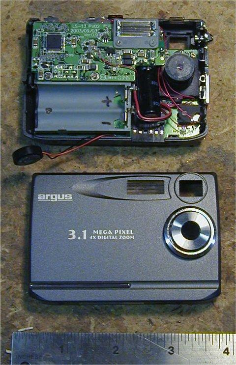
The micro switches that come with the camera for the shutter and on/off are very tiny and hide the connections that will have to be made to enable the shutter and WAKEUP (on/off) functions to be triggered electronically. If you want to set this camera up for that, you will need to remove the old switches and solder on new ones with extra contacts. The switch shown can be bought from most electronic supply stores and are designed to be mounted on printed circuit boards. They fit fine, but you will need to add potting compound or hot-melt glue (as pictured) to support them. You will also need to remove part of the top of the camera case to allow for their larger size. Be careful, the silver case highlites in the Argus camera case conduct electricity and these two switches should not have a circuit between them. |
RC-Cam's Aiptek Pencam PIC switch is a remarkable and simple device that allows you to electronically close the shutter on digital camera via a spare RC channel. It monitors the spare channel and when it goes from low to high (like a retract switch would cause), the PIC drives the shutter line to gound momentarily. On most cameras this shutter line can be soldered to the SHUTTER switch on the camera, allowing for pictures to be taken remotely. This is only the case if the SHUTTER button drives the connection to ground, but I have yet to find a digital camera where this is not the case.
Some cameras have a sleep function that turns the camera off after some set amount of time to save battery life. If the camera is off, the shutter line by itself won't do any good; the camera must be turned on and this sleep feature must be overcome. The Aiptek Pencams all have ground-enabling wakeup buttons. In other words, to turn on the camera the ON button drives the connection to ground. Because of this, MR-RC-Cam's wakeup function drives the WAKEUP line to ground. These cameras will also have circuitry that must be traced to find an AWAKE line. An AWAKE line is active high (+3 volts) when the camera is on and 0 volts (or very low) when the camera is off. This AWAKE contact point must be located for each camera as they are different for every model. This AWAKE line is monitored by the PIC and if the line is low, the camera is off, and the PIC must drive the WAKEUP line to ground to turn the camera ON. Once the camera is on, the AWAKE line is high and the SHUTTER line can be momentarily driven to ground to take a picture.
I wrote an alternate version of CamMan, but it does away with the AWAKE monitoring and instead takes pictures automatically to keep the camera alive. This keep alive version is the one I have included in the final configuration for this camera. If you want to modify the code to do things a little differently, please see my PIC Development page for full details on how to use this code in your own configuration.
CamMan Copy with Inverted Wakeup
You can use the standard CamMan for this camera, with the exception of the WAKEUP function. The CamMan drives the Wakeup line to ground to turn the camera on, which is backwards for this camera. So I wrote my own version of the CamMan which does the opposite. My version is almost identical to CamMan, the only difference is that it drives the WAKEUP line high for this particular camera. You will also need to add a transisitor to the Wakeup line to carry the required current, because the PIC can not drive enough current by itself. The circuit below shows all the connections.
| Source code: camman_copy_inverted_wakeup.bas | HEX: camman_copy_inverted_wakeup.HEX |
| My inverted wakeup version for the DC3640 camera works like this: | Inverted wakeup circuit: |
| Init: Flash LED 3 times Monitor the PWM signal from the RC receiver Wait for a complete cycle (low - high - low) to begin the next step Loop: Take a picture: |
 |
Internal Power and Standard CamMan
If you do want to use the CamMan standard configuration, with the internal batteies for power, you will need to invert the WAKEUP signal. This can be done a number of ways, but the simplest is with a transistor and two resistors. This circuit on the left below is a NOT gate. If the input is high, the transistor connects the collector to the emitter and the output is tied to ground. If the input is low, the transistor does not connect the collector to the emitter and the pull-up resistor keeps the output high. Adding a second input to this circuit makes it into a NOT-AND or NAND gate, the basis for all modern logic circuits. Because the Argus DC3640 is using the current flowing through the final connection to activate the camera and there is a current limiting resistor in the final stage, this circuit by itself is not enough to turn the camera on. A second transistor must be used with no current limiting resistor; it is turned on by the output of the first stage of the circuit. That circuit on the right below works well to turn on the Argus.
 |
 |
External Power and Standard CamMan
Before I wrote the keepalive version that I finally settled on, I had a small external board that provided +3 volts via a voltage regulator, and the PIC switch was included on that board. This board was shared between the Argus and Dakota cameras, both of which had the same power requirements and inverted wakeup logic. Many digital cameras can have the +5 volts from the RC receiver go directly into their USB connectors, where a voltage regulator converts it to what is needed. As it turns out, the Argus and Dakota both have active high wakeup circuitry, and both also have a little feature which makes the USB power connection useless. When power comes into the USB connector, the cameras become storage devices that are visible as external drives by Windows; they can no longer take pictures. That leaves two options: leave the batteries in the camera or provide 3 volt power supply directly to the battery contacts. If you don't want to carry the extra batteries in the cameras, this is easly accomplished with an LM317 variable voltage regulator and two resistors. One resistor is fixed and the other is a variable resistor or potentiometer. Alternately, MAXIM has a fixed 3.3 volt low dropout voltage regulator that takes anywhere from 3.6 volts and up, to give a steady 3.3 volts. I have used that fixed 3.3 volt regulator and it works well. I also had the inverting circuit for the Wakeup signal on this external board, so the standard CamMan could be used.
|
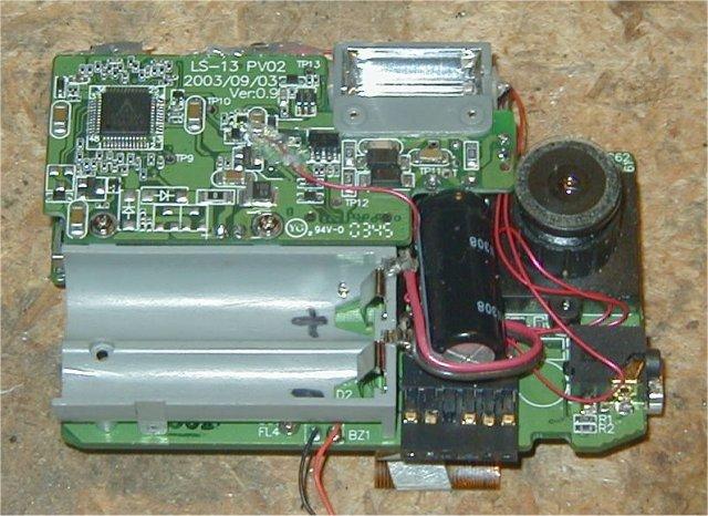
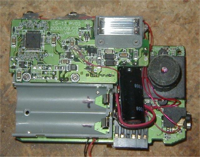
You can see here the connections required, other than the shutter and on/off switches which are shown above. The AWAKE pinout is the surface mount capacitor on the center of the flash daughterboard. It is at Vcc (+3 volts) when the camera is AWAKE, but drops below 1 volt when the camera is asleep. The +3 and ground pinouts go right to the battery terminals. If you solder external power to the USB connector, the camera will think it is connected to a computer and will only act as a storage device. With this configuration, I had made a connector to run +3 Volts, GND, AWAKE, WAKEUP, and SHUTTER to the external board shown below. |
|
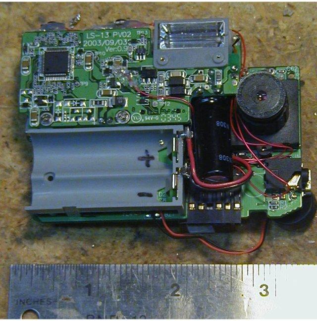
Since there is not much room inside the camera, and I originally wanted to
share a setup between this camera and the Dakota, I ran all five connections to a small
plug. This connector is a standard .1" pitch connector with 6 connections.
I leave one empty and fill it with glue, then remove the corresponding pin on the
male side. That allows the male connector to be plugged in only one way.
Pictured here, you can see the size of the connector and where it can fit beneath the
flash capacitor. Note: Because I used only a keep-alive version with no inverting transistors in the final setup, I was able to fit the keep-alive version of the 12C508 PIC inside the camera by removing this connector. The Dakota also received its own keep alive switch internally. They have different timeout periods; the Dakota's timeout is 1:30, while the Argus' timeout is 25 seconds. |
|
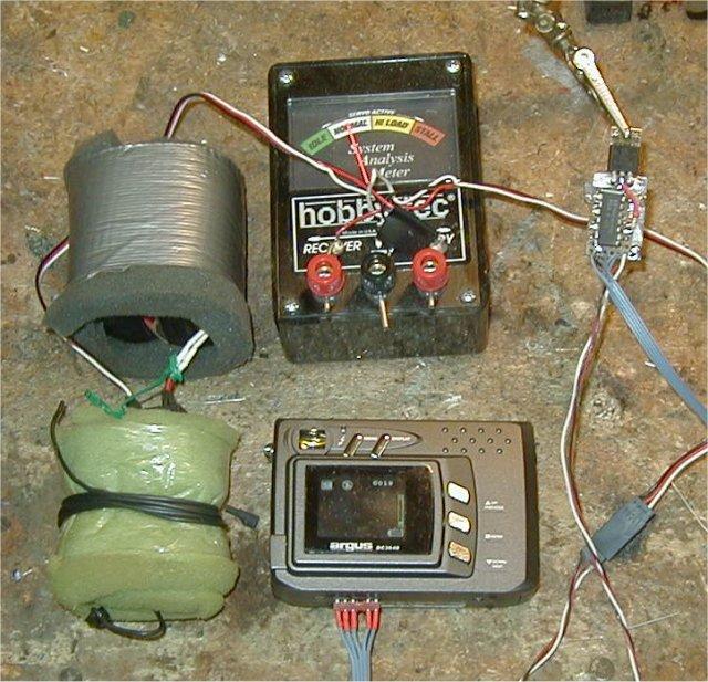
The external board I had made gets its 5 volts supply from the receiver, along with ground and the RC channel input used to control the switch. I have monitored the current draw for the entire setup with a servo current test device. With the digital camera on and its LCD screen on also, the current draw is in the medium to high normal range for a standard servo. If the LCD screen is off, the current draw stays in low normal range all the time. |