Lastly, you need the PIC itself. They can be bought from just about any electronics supply house. I have used Mouser with no problems. The 12C508A is $1.02 each in quantities less than 25.
There are literally thousands of web pages that speak to writing code for a PIC, programmable integrated circuit. I will concentrate on what you need to do to create a switch for use with remote control and a digital camera using a 12C508 PIC. It is very easy to glue or mount a hobby servo to a digital camera to take aerial photos, but it is also very easy to do the same thing with a little bit of solder and a PIC, and it is much lighter and more elegant. MR. RC-Cam's CamMan switch got me started in this area. If you are going to modify one of the cameras listed on his pages, or a camera with similar characteristics for shutter circuit, on/off circuit, sleep cycle, wakeup function, etc., use his CamMan switch. I have made many and installed them into lots of cameras. It is a great design and consists of a single PIC, capacitor, and resistor.
If the camera you are working on needs specific functions to work via a PIC, you may want to try and program a PIC for yourself. The design I present here uses the same hardware as the CamMan, but has slightly different software which you can modify. All the software to do this is free to download and the hardware can be bought for less than $20, including the PIC programmer.
Hardware
|
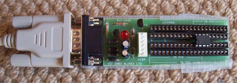
You will need a hardware PIC programmer, a serial extension cable, and the
PIC itself. I use the JDM PIC programmer. The design is available for free and you could build
it yourself, but you can buy a ready made version from Sparkfun for $12.95.
That is probably less than the parts themselves would cost at a Radio Shack. This
programmer plugs into the serial port on your PC. You do need a real serial port (9
pin DSUB connector) on your PC. A USB to serial port adaptor has shown to cause
problems with the power provided through the USB connector. Since the serial port is
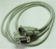
probably on the back of your computer, you need a serial extension cable to run to the
front where you can work with the programmer. You can buy that extension at Sparkfun for $2.95. Lastly, you need the PIC itself. They can be bought from just about any electronics supply house. I have used Mouser with no problems. The 12C508A is $1.02 each in quantities less than 25. |
Software
There are several steps in the software process; you will need a compiler to convert your
high level PICBasic code into the machine language the PIC can run, the PIC programmer
software, and a beginning program if you don't want to start coding from scratch. My
code is available below for free.
The compiler is free from Proton. It is the Proton IDE (integrated development environment) Lite. The Lite is what makes it free. The free version only works for a few PICS, but it works with the 12C508; the one we will be using. The output of this compiler is a HEX file. Think of this as an .exe file for a PC. It is the executable that must be run on the PIC.
The programmer software takes the HEX file and burns it to the PIC. The best programmer software I have found is IC-Prog. It works with several hardware programmers, and Sparkfun has a tutorial page on its use with the JDM programmer. As a bonus, IC-Prog and the JDM programmer will work with many other PICs for other projects.
PIC Switch Functions
Mr. RC-Cam has several versions of his PIC and each one does its job slightly differently. I.E. drive to Vcc instead of ground, no AWAKE monitoring, etc. Please check his web page for a detailed explanation of each version. My keepalive version is functionally about the same, but it does do a few things slightly differently. It does not monitor an AWAKE input line and use a WAKEUP output line to activate the camera if it goes to sleep. Instead it automatically takes a picture to keep the camera awake if you fail to do so manually after a set timeout period. I had problems getting the wakeup function to work reliably on a few camers, so I went to this "always on" mode for those cameras.
The source code and compiled HEX have a timeout when the counter reaches 900.
That can be modified in the code. The counter limits I have used so far are shown
below. Use these to adjust your timeout period. I still have not figured out
why cycles / second is not constant.
waitcounter = 900 -> 23 seconds = .02555 cycles / second
waitcounter = 4200 -> 96 seconds = .02285 cycles / second
waitcounter = 4700 -> 107 seconds = .02276 cycles / second
| The CamMan PIC works about like this: | My keepalive version works like this: |
| Init: Monitor the PWM signal from the RC receiver Wait for a complete cycle (low - high - low) to begin the next step Loop: Take a picture: |
Init: Flash LED 3 times Monitor the PWM signal from the RC receiver Wait for a complete cycle (low - high - low) to begin the next step Loop: Take a picture: |
| Source: Not Released | Source: cam_switch_keep_alive.bas |
| HEX: RC-Cam's CamMan Project | HEX: cam_switch_keep_alive.HEX |
I also have two more versions for download, the first being a copy of CamMan with the LED functionality from my keepalive version added. The second version has inverted wakeup logic, coded specifically for the Argus DC3640 digital camera, where the Power switch connects to Vcc instead of Ground. That inverted version requires an extra transistor, because the 12C508 can not drive enough current by itself to wake up the camera. Please see my Argus webpage for full details.
| My copy of the CamMan with LED added: | My inverted wakeup version for the DC3640 camera works like this: |
| Init: Flash LED 3 times Monitor the PWM signal from the RC receiver Wait for a complete cycle (low - high - low) to begin the next step Loop: Take a picture: |
Init: Flash LED 3 times Monitor the PWM signal from the RC receiver Wait for a complete cycle (low - high - low) to begin the next step Loop: Take a picture: |
| Source: camman_copy.bas | Source: camman_copy_inverted_wakeup.bas |
| HEX: camman_copy.HEX | HEX: camman_copy_inverted_wakeup.HEX |
The hardware pinout of a PIC12C508 is defined at the beginning of the code. Study the different versions of the code and modify it to try something new; longer timeout, different pins, more LEDs, different logic, whatever... Use Proton IDE Lite to compile it. After you have the logic to what you want and it compiles correctly, take that HEX file and inport it into IC-Prog. If any of these versions are exactly what you want, use the already compiled HEX code in IC-Prog.
|
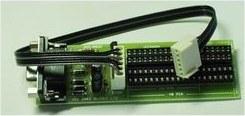
Attach the JDM programmer to your PC using the serial cable, and then plug in your PIC 12C508. Pay careful attention to how the 8 pin device plugs in. |
Open IC-Prog and set the device type to 12C508. Open the HEX file you want to use. Burn it. It will ask you if you want to override the internal clock - answer NO. Do not remove the PIC until the light goes out. You are done. Solder it all together and test it out before you install it into the camera. The LED will aid in debugging.
GPIO Definitions and Pseudocode
| The code above uses GPIO.0 through GPIO.5 to drive and read the pins on
the PIC. Those definitions are shown to the right. The complete psuedocode for my keepalive version is below on the left and makes use of an ancient software algorithm, the state machine. The version on the right below is simplified by removing redundant code. |
 |
| 12C508 Digital Camera Switch Psuedocode State 0 = just starting 1 = was in state 0, PWM now at low 2 = was in state 1, PWM now at high 3 = was in state 2, PWM now at low, ready to take picture 4 = was in state 3, PWM now at high, taking or took picture, need to reset to low to enable another picture Init: ReadPwm: if no signal, goto init if state = 0: (stick at ??, initial state on startup) if state = 1: (stick at low) if state = 2: (stick at high) if state = 3: (stick at low, ready to take pic) if init state = 4: (stick at high, pic was taken) takepic: |
Init: Init state = 0 blink LED 3 times ReadPwm: if no signal, goto init (no signal - blink the LED) if state = 0 (stick position undetermined, initial state on startup) then if state = 1 (stick at low) then if state = 2 (stick at high) then if state = 3 (stick at low, ready to take pic) then if state = 4 (stick at high, pic was taken) then goto readpwm waitcounter: takepic: |