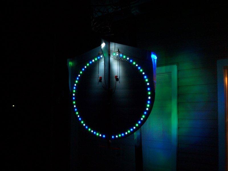
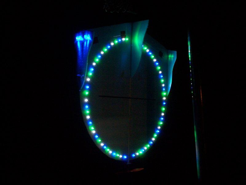
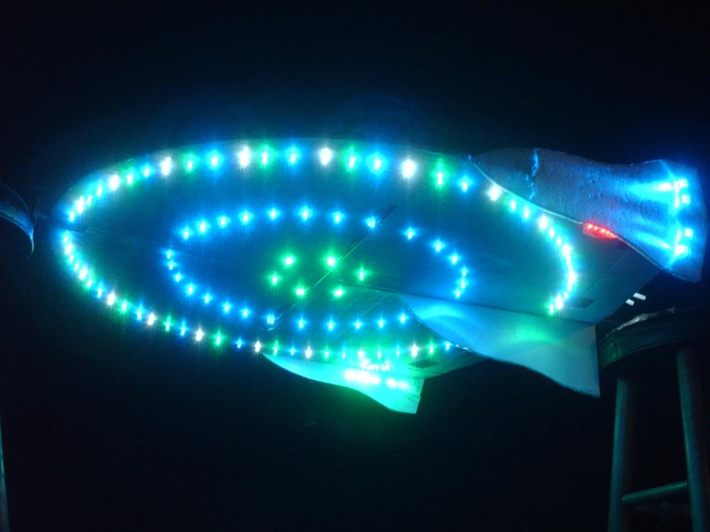
UFO Blue - old version with no flashing - The first version of the UFO night flyer had fixed LEDs, and could be seen to several hundred feet at night. The blue LEDs are the brightest, and they lit up the ground easily. The UFO created a circle of light on the ground. I then added 50 more LEDs from my retired Slow Stick night flyer, so the UFO had 150 LEDs, with the main section of lights in three concentric circles. When I later reworked the LEDs on this UFO to use strips and LED spotlights, I moved all the individual LEDs onto home-made strips of three each, and installed those inside Blue Wing #2, which is detailed below.
I was inspired by this thread at RCGroups for my UFO flying disk:
http://www.rcgroups.com/forums/showthread.php?t=762714
The bright LEDs were bought from http://abctronics.com/ I have used these LEDs:
Red 3mm: 2700 millicandles, 20 ma average current, 30 ma max current, forward
voltage = 1.95 volts
Blue 5mm: 4500 millicandles, 20 ma average current, 30 ma max current, forward
voltage = 3.15 volts
White 5mm: 9000 millicandles, 20 ma average current, 30 ma max current, forward
voltage = 3.15 volts
Green 5mm: 10000 millicandles, 20 ma average current, 30 ma max current, forward
voltage = 3.10 volts
If you want to do something similar, buy your LEDs, take the forward voltage for each LED, the average operating current of 20 ma, and plug them in with your source voltage to the LED calculator here: http://www.rc-cam.com/led_info.htm That will give you the resistor you need to solder in series with each LED.
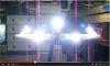
Video Demo
at YouTube
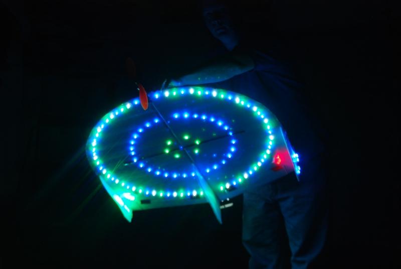
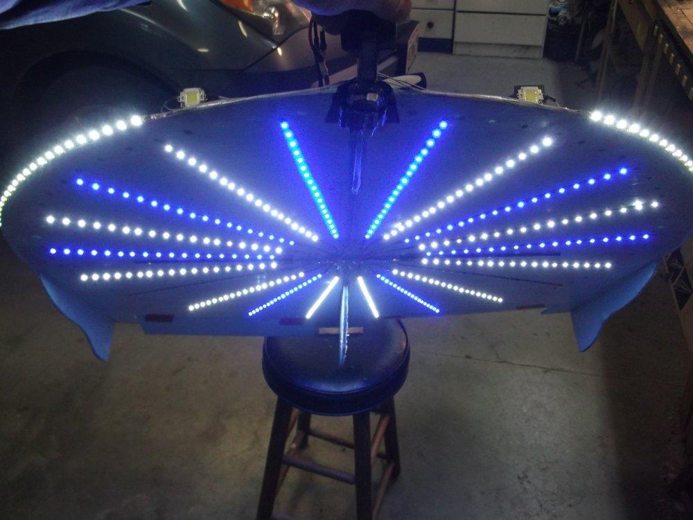
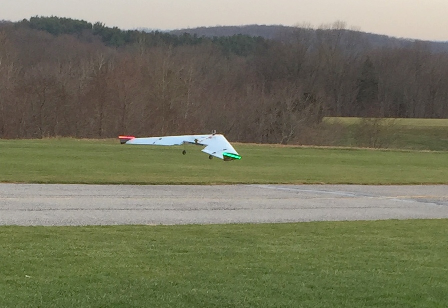
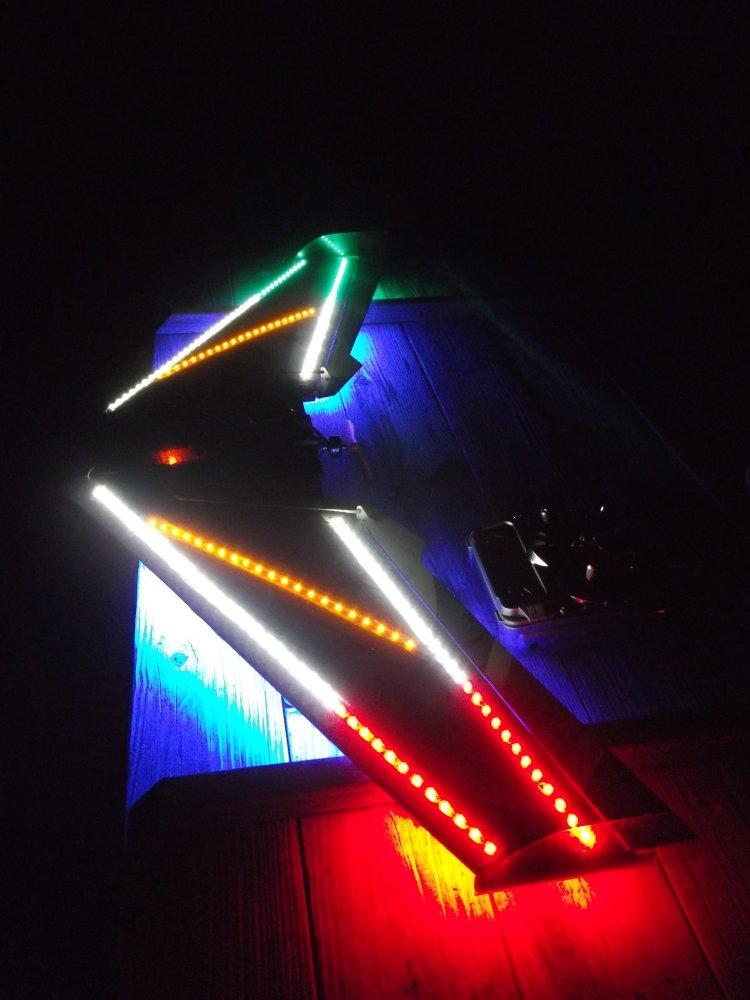
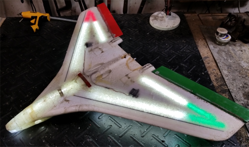
UFO Blue LED - current version - I later modified the UFO, adding three separate LED sections (#1- #3 below). The lights on this version are dazzling and can be seen from several thousand feet. All power comes from the main 3S 2650 mah lipo battery pack.
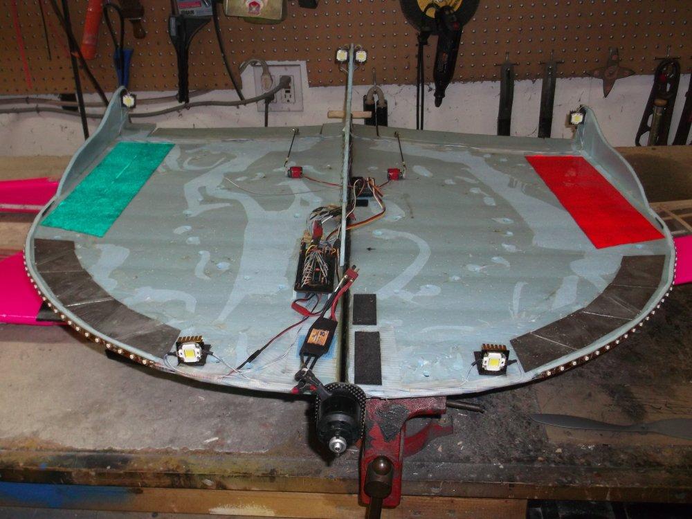
#1 - Fixed white, red, and green LEDs that cover the
leading edges and wingtips. This set is always on.
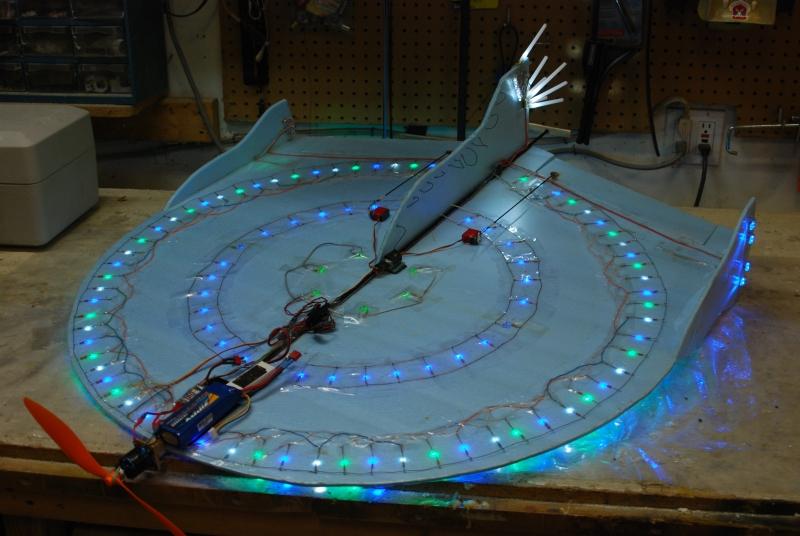
#2 - Two circular sections of alternating blue and white LEDs that rotate at a
variable speed controlled via an RC channel from the ground. These 20 banks of
LEDs are connected in pairs on the left and right of the bottom of the UFO, with
ten sections on each side.
#3 - Three banks of two super bright LEDs each (rated at 1 watt each), for a total of six super bright
LEDS, individually commanded via a second RC channel from the ground.
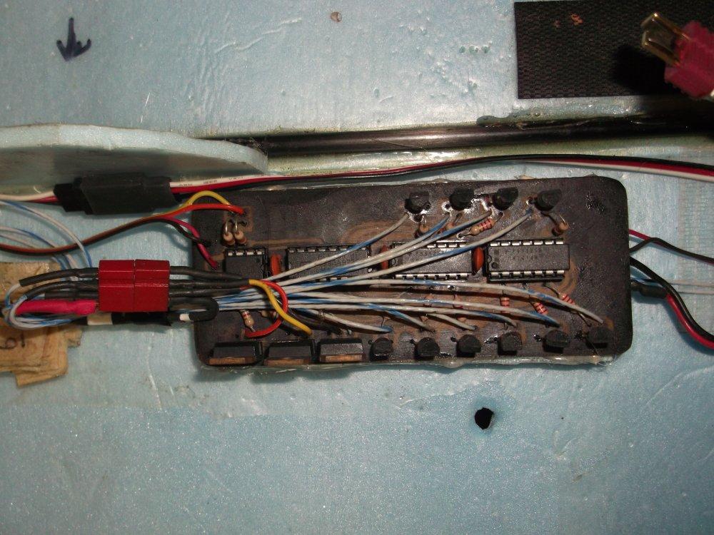
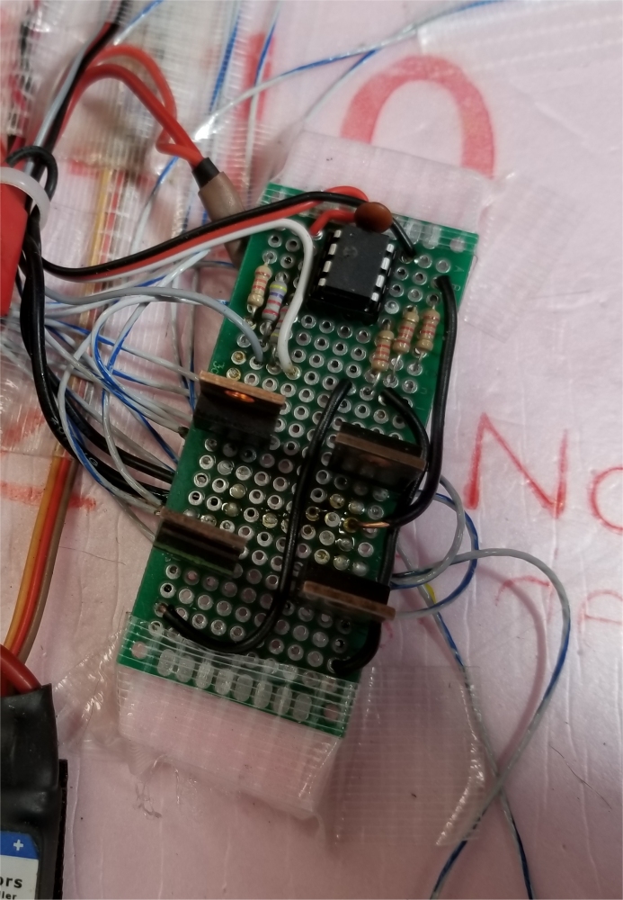
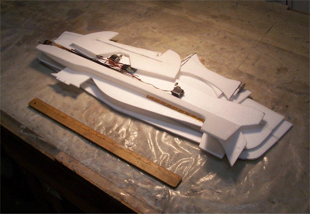
A home made on-board sequencer control LED sets #2 and #3. It is shown in the third photo on the left, and is made up (from left to right in the photo) of a 12C508 PIC running custom code, a decade counter, and two inverters. Across the top and bottom of the board are ten 2222 transistors, three TIP122 transistors, and various resistors and caps. The PIC has two PWM inputs, and four digital outputs that drive the decade counter and transistors.
- PWM input 1: timing input: receives 1 - 2 ms PWM signal that determines flashing rate
- PWM input 2: four positions:
< 1.25 ms = all three banks of super bright LEDs off
1.25 - 1.5 ms = flashing type 1, one group at a time - sequence super bright LED group 1
--> 2 --> 3 --> 1 --> 2 --> 3 ...
1.5 - 1.75 ms = flashing type 2, all groups together - all groups on --> all groups off
--> all groups on --> all groups off ...
> 1.75 ms = all three banks of super bright LEDs on
Input 2 is controlled by two switches on radio:
Switch 1 = 3 position = 1 ms, 1.5 ms, 2 ms
Switch 2 = 2 positions = mix in .1 ms above or below 1.5 ms (-> 1.4 or 1.6 ms)
for flashing type
Digital output 1: single pulse at flashing rate that goes to decade counter
Digital outputs 2 - 4: on/off for each transistor for each superbright LED bank (2
LEDs each)
The source code for the Blue UFO LED sequencer is here. The wiring schematic is here.
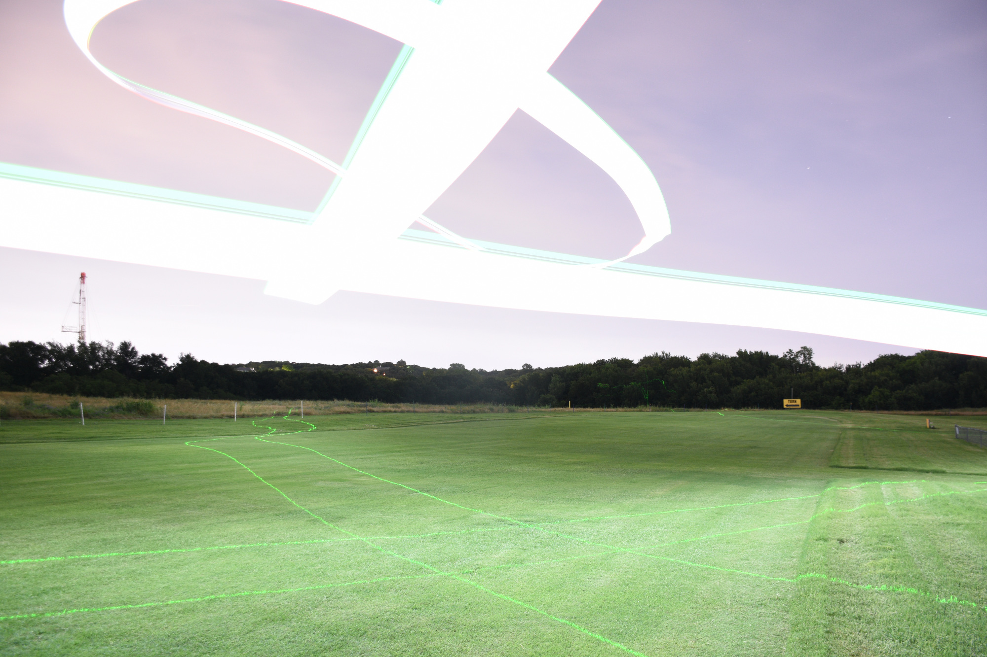
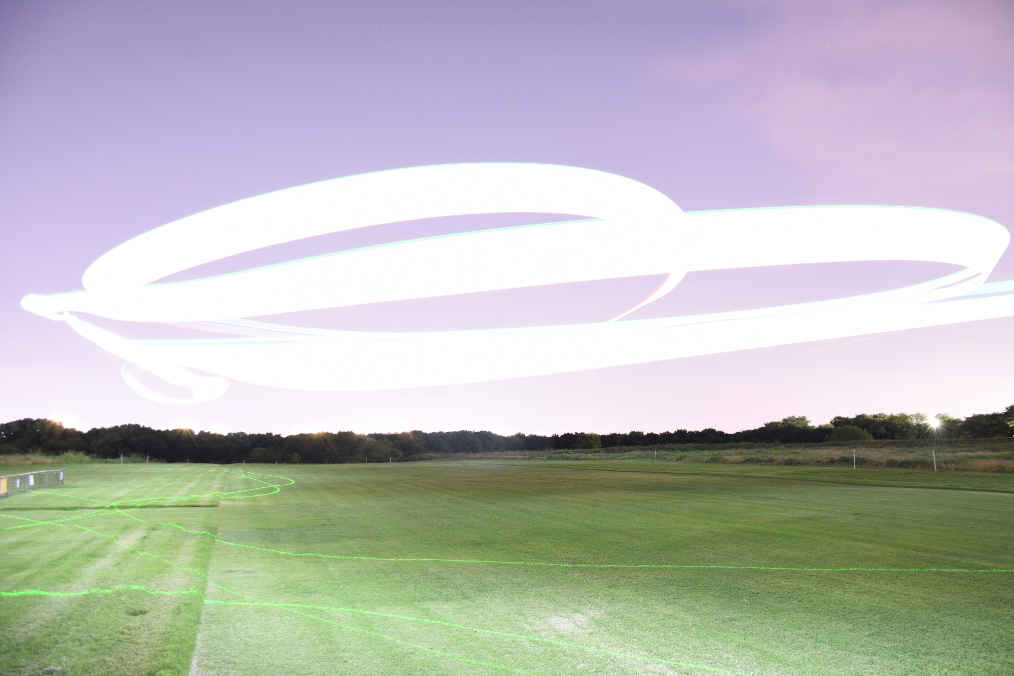
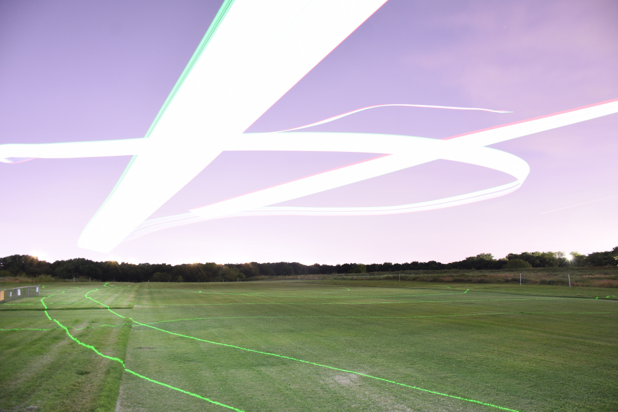
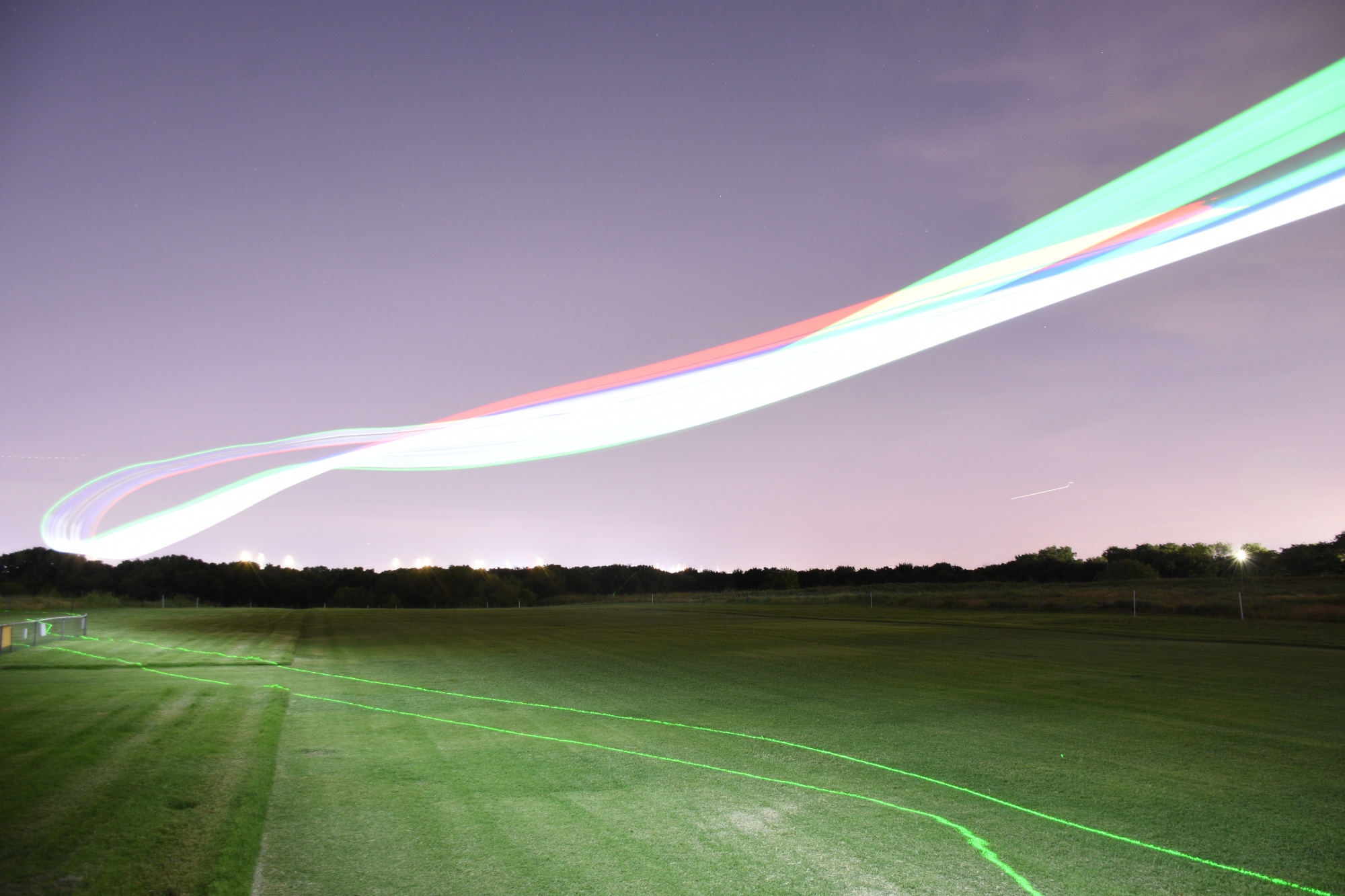
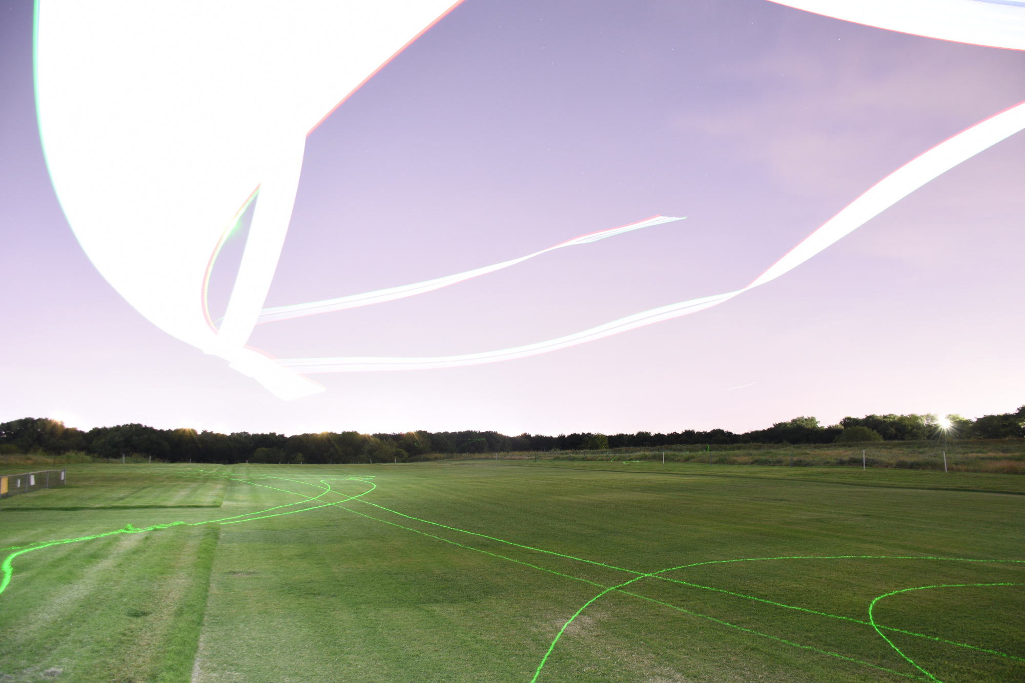
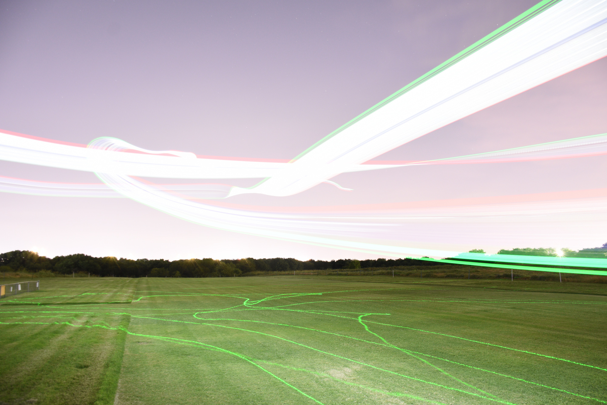
I added eye-safe green lasers to this plane and the Blue 6' Wing below in November 2025. These videos show these planes in action with their lasers.
Maryland <--
Blue UFO and Blue 6' Wing with Green Frickin' Lasers --> Texas
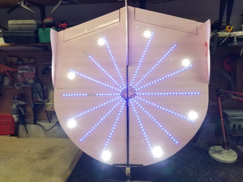
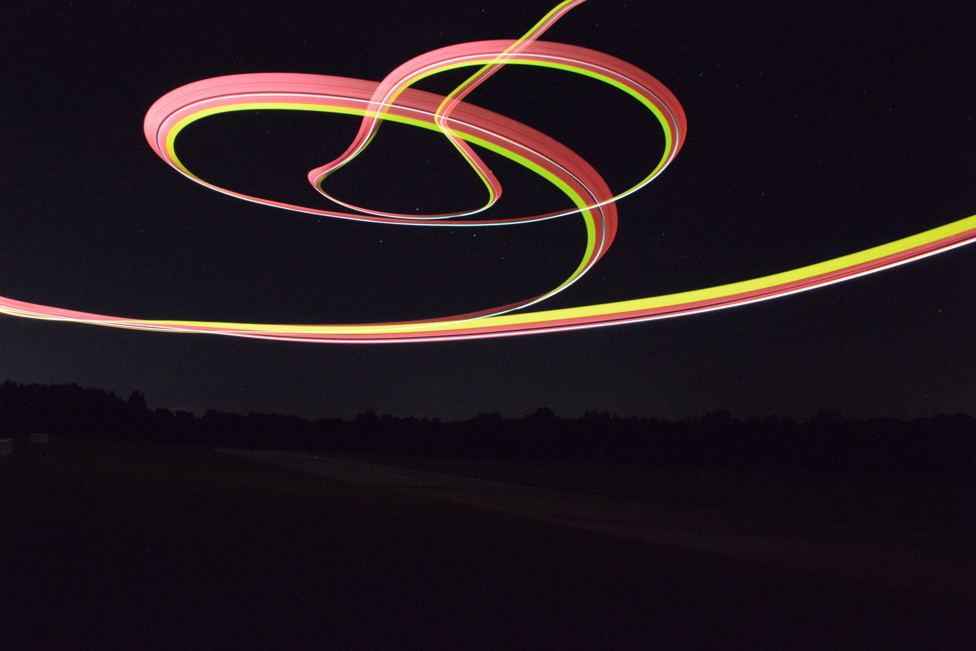
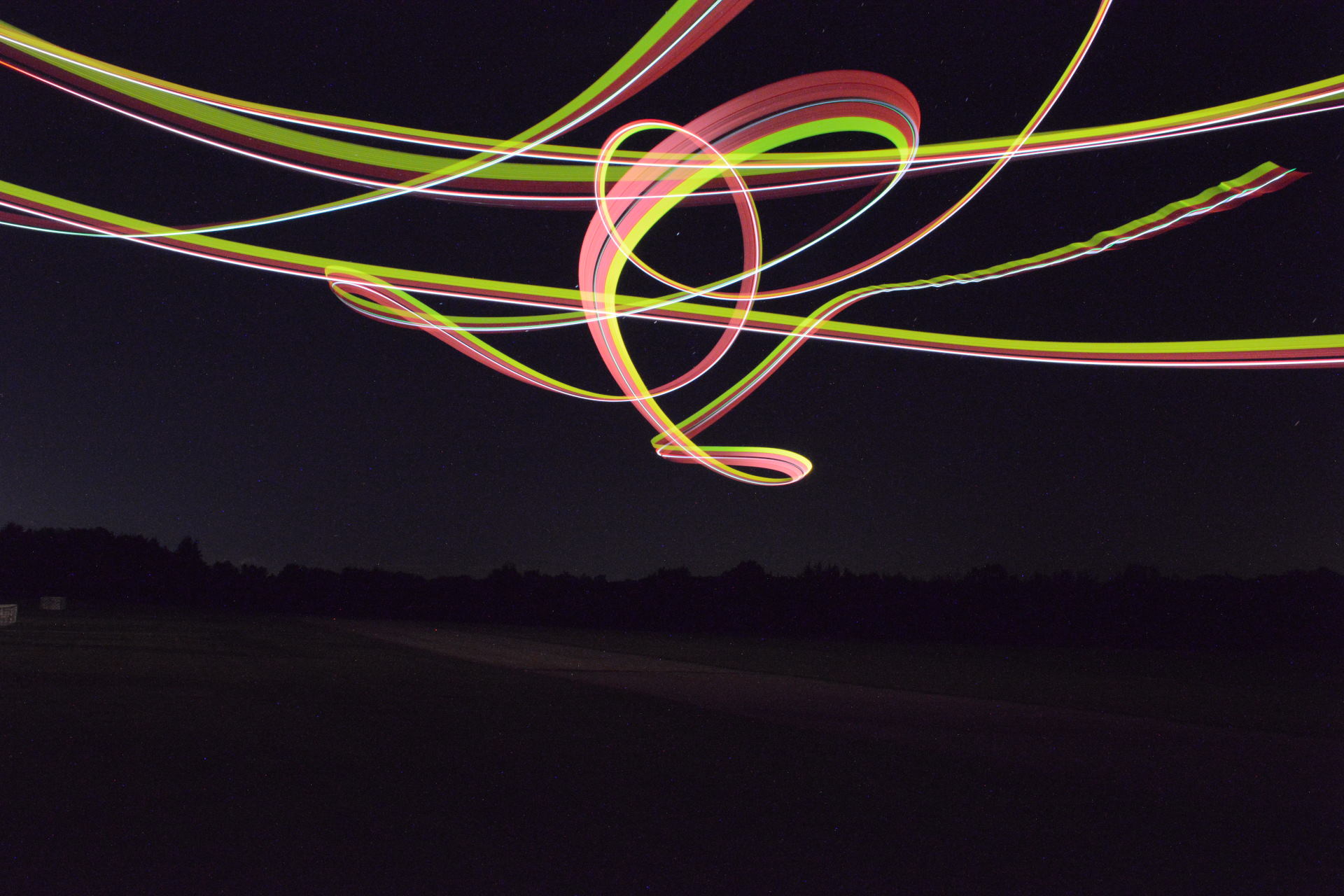
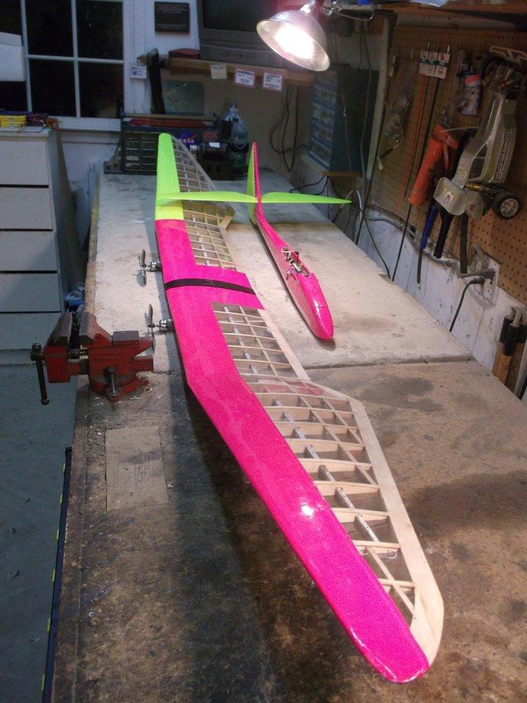
UFO Pink LED - The pink UFO has fixed sets of LEDs, and 8 super-bright LEDs facing straight down along the circumference of the UFO circle. These super-bright LEDS are tied together in pairs, opposite each other, for a total of 4 banks of LEDs.
A home made on-board sequencer controls the super-bright LEDs. It is made up of a 12C508 PIC running custom code driving four TIO120 transistors. The PIC has two PWM inputs, and four digital outputs that drive the LEDs through the transistors.
- PWM input 1: timing input: receives 1 - 2 ms PWM signal that determines flashing rate
- PWM input 2:
< 0.96 ms = all four banks of super-bright LEDs off
0.96 - 1.12 = all four banks flash together
1.12 - 1.27 = all flash in circle clockwise, one
light on at a time ( 1 .. 2 ... 3 .. 4 .. 1 .. 2
.. 3 .. 4 ...)
1.27 - 1.41 = all flash in circle
counterclockwise, one light on at a time ( 4 ..
3 .. 2 .. 1 .. 4 .. 3 .. 2 .. 1 ...)
1.41 - 1.57 = flash back and forth, one light on
at a time ( 4 .. 3 .. 2 .. 1 .. 2 .. 3 .. 4 .. 3
.. 2 .. 1 .. 2 .. 3 .. 4 ...)
1.57 - 1.71 = all flash in circle clockwise, one
light off at a time ( 1 .. 2 ... 3 .. 4 .. 1 ..
2 .. 3 .. 4 ...)
1.71 - 1.86 = all flash in circle
counterclockwise, one light off at a time ( 4 ..
3 .. 2 .. 1 .. 4 .. 3 .. 2 .. 1 ...)
1.86 - 2.02 = flash back and forth, one light
off at a time ( 4 .. 3 .. 2 .. 1 .. 2 .. 3 .. 4
.. 3 .. 2 .. 1 .. 2 .. 3 .. 4 ...)
> 2.02 ms = all four banks of super-bright LEDs
on
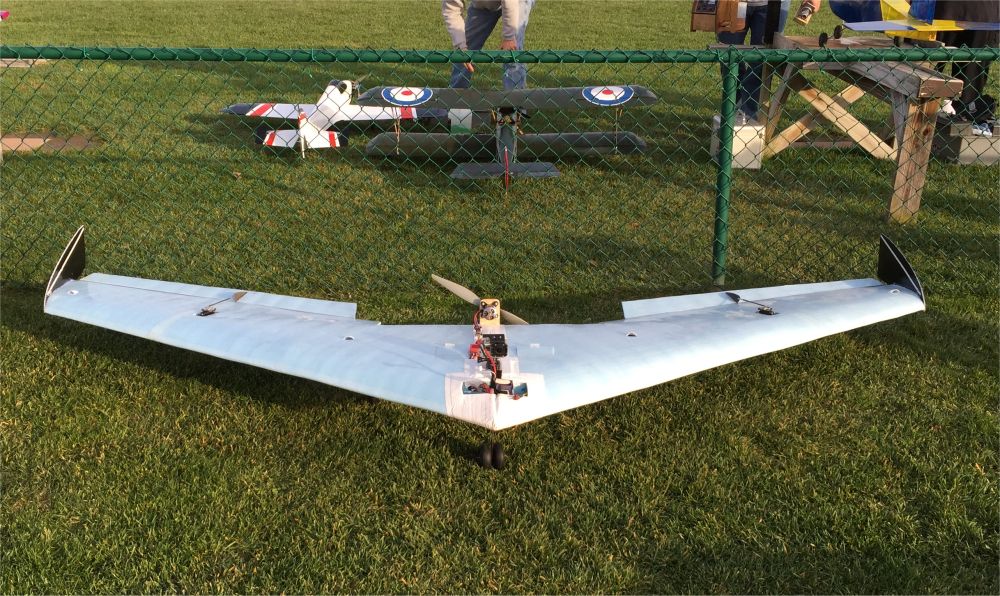
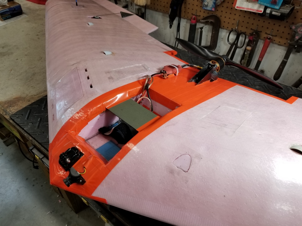
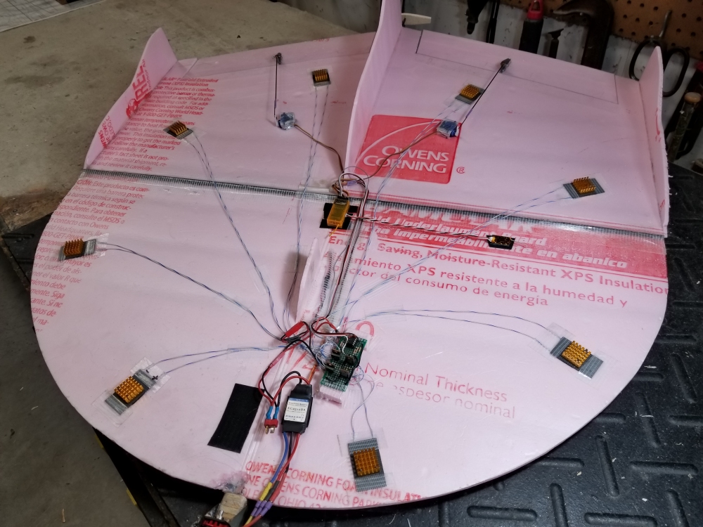
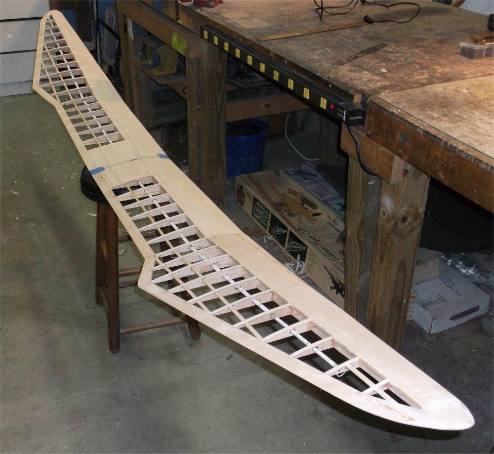
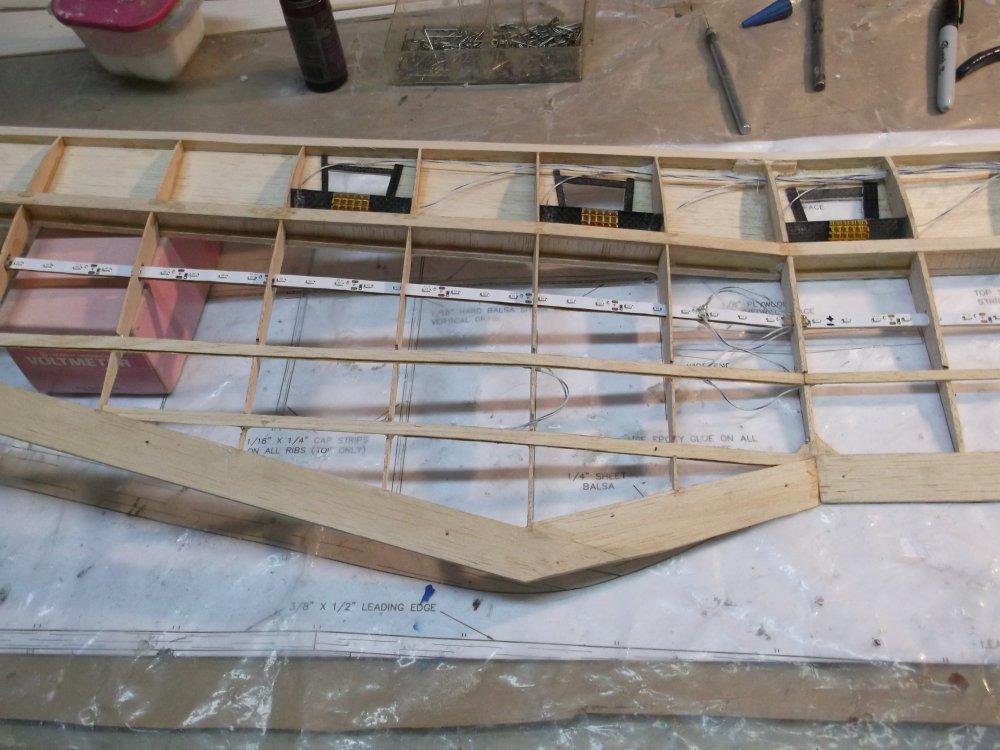
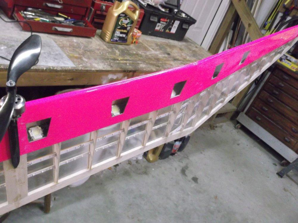
8.5' Pink Wing LED - The 8.5' pink wing has 6 super-bright LEDs facing straight down. The two center LEDs are tied together as a single light source, for a total of 5 separately controllable light sources.
A home-made sequencer with variable speed, on/off, and alternating sequences controls the super-bright LEDs. It is made up of a 12C508 PIC running custom code, and five TIP120 transistors, and various resistors and caps. The PIC has one PWM input, and five digital outputs that drive the transistors.
- PWM input:
< 1.05 ms = all off
1.05 - 1.50 ms = all LEDs flash together at variable rate, one off, speed depends on 45 ms range from 1.05 - 1.5 ms
1.50 - 1.95 ms = cycle back and forth like NightRider, one on, speed depends on 45 ms range from 1.5 - 1.95 ms
> 1.95 ms = all on
- Digital outputs 1 - 5: on/off for each transistor for each super bright light source
The source code for the Pink Wing LED sequencer is here. The wiring schematic is here.
Video Demo
at YouTube
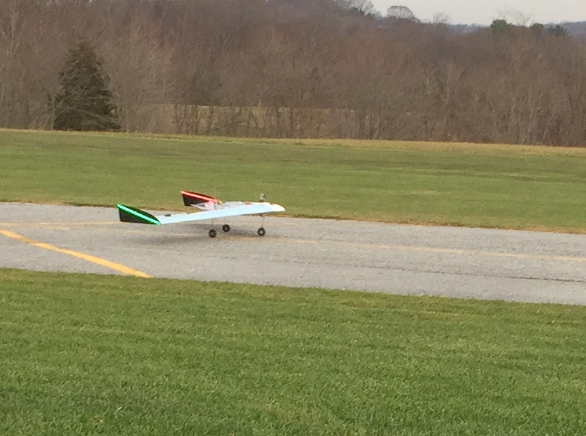
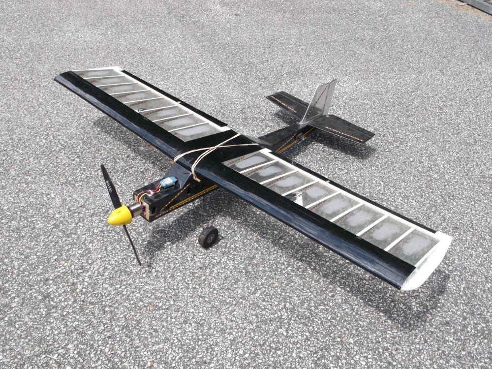
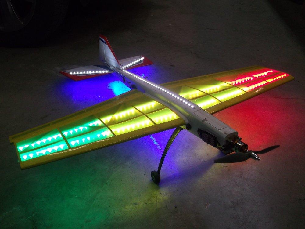
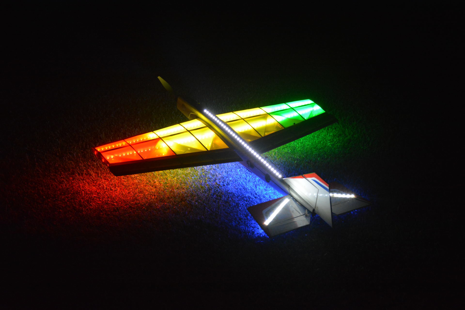
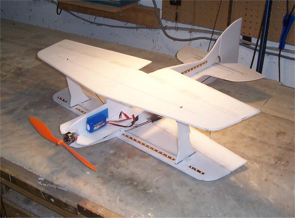
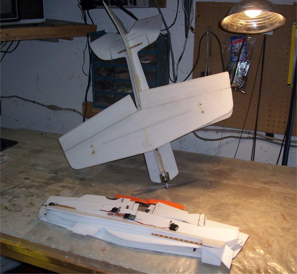
Night Trainer LED - This plane is covered with several separate LED sections (#1 - #3 below). LED power comes from an independent 3S 2200 mah lipo battery pack. The motor and RC electronics are powered by a separate 5S 3000 - 5000mah lipo battery pack.
#1 - Fixed blue, white, red, and green LEDs that fill the inside of the wing,
and cover portions of the fuselage. This set is turned on/off via a switch on
fuselage.
#2 - There are over five meters of red/green/blue LED strips, 60 LEDS/meter,
with a commercially pre-programmed controller with flashing and sequencing built
in, controlled via a hand-held IR remote control. This set was bought on
ebay, and the sequencer was removed from its large case and potted to insulate
it for installation in the fuselage.
#3 - Five banks of super bright LEDS, four on each wing side leading edge, plus
one LED + extra white LEDS on fuselage center surrounding motor, for a total of
nine super bright LEDs. These five banks are controlled via a RC channel
from the ground.
A home-made sequencer with variable speed, on/off, and alternating sequences
controls LED set #3. It is made up of a 12C508 PIC running custom code, five
TIP120 transistors, and various resistors and caps. The PIC has one PWM
input, and five digital outputs that drive the transistors.
- PWM input:
< 1.10 ms = all on
1.10 - 1.50 ms = cycle back and forth, one off, speed depends on 40 ms range
from 1.1 - 1.5 ms
1.50 - 1.90 ms = cycle back and forth, one on, speed depends on 40 ms range from
1.5 - 1.9 ms
> 1.90 ms = all off
- Digital outputs 1 - 5: on/off for each transistor for each super bright LED bank
The source code for the Night Trainer and Bird of Time LED sequencers is here. The wiring schematic is here.
Bird Of Time LED - This plane has two separate sections of LEDs. All power comes from the main 3S 4000 mah lipo battery pack.
LED section #1 - The wings are filled with over five meters of blue LEDS, with green & red
LEDS at the wing tips. The fuselage is covered with two meters of red
LEDs. This set is on all the time.
LED section
#2 - Five banks of super bright LEDS, five inside each wing side leading edge,
for a total of ten super bright LEDs. These five banks are controlled via
a RC channel from the ground.
A home-made sequencer with variable speed, on/off, and alternating sequences
controls LED set #2. It is made up of a 12C508 PIC running custom code,
five TIP3055 transistors, and various resistors and caps. The PIC has one
PWM input, and five digital outputs that drive the transistors.
- PWM input:
< 1.10 ms = all on
1.10 - 1.50 ms = cycle back and forth, one off, speed depends on 40 ms range
from 1.1 - 1.5 ms
1.50 - 1.90 ms = cycle back and forth, one on, speed depends on 40 ms range from
1.5 - 1.9 ms
> 1.90 ms = all off
- Digital outputs 1 - 5: on/off for each transistor for each super bright LED bank
The source code for the Night Trainer and Bird of Time LED sequencers is here. The wiring schematic is here.
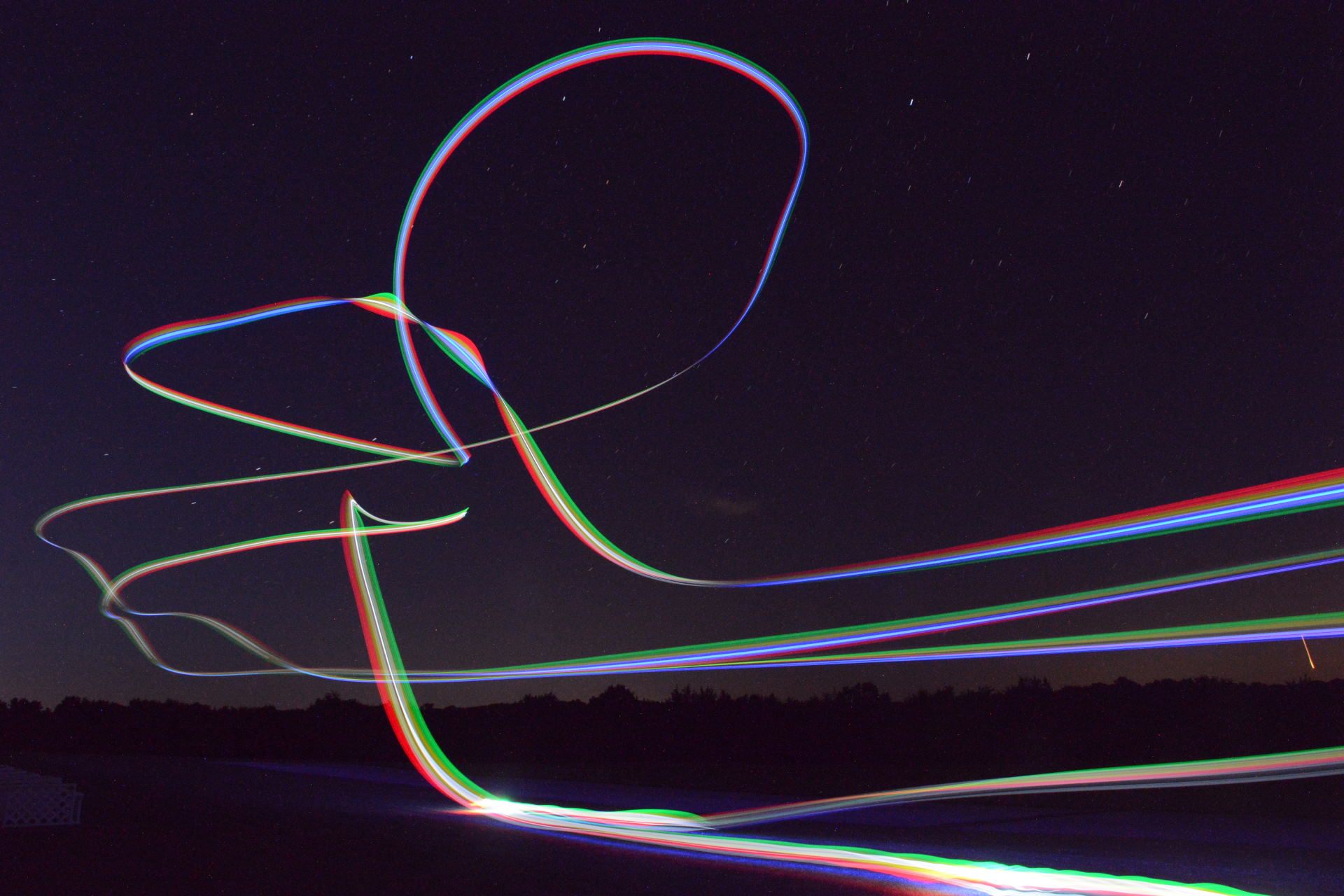
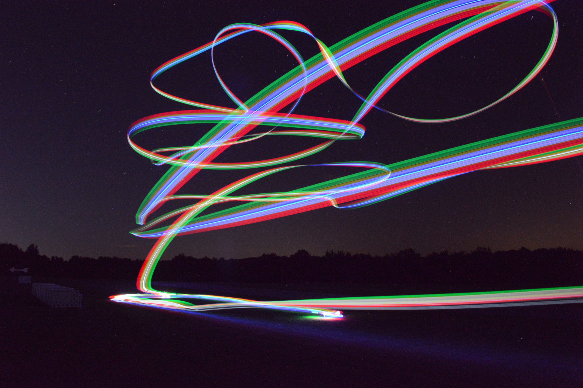
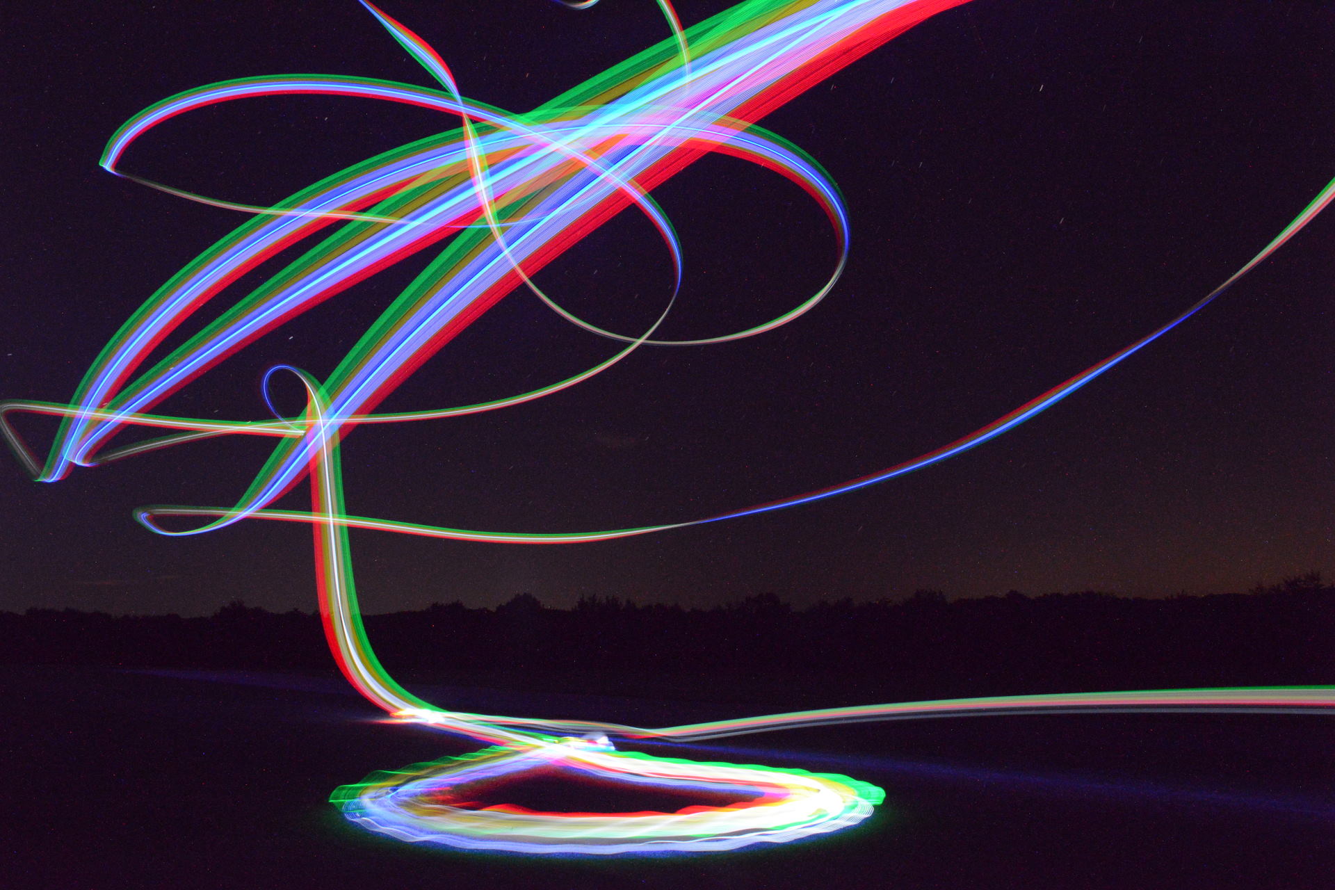
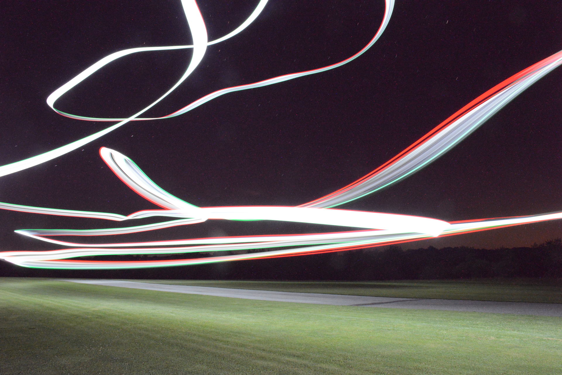
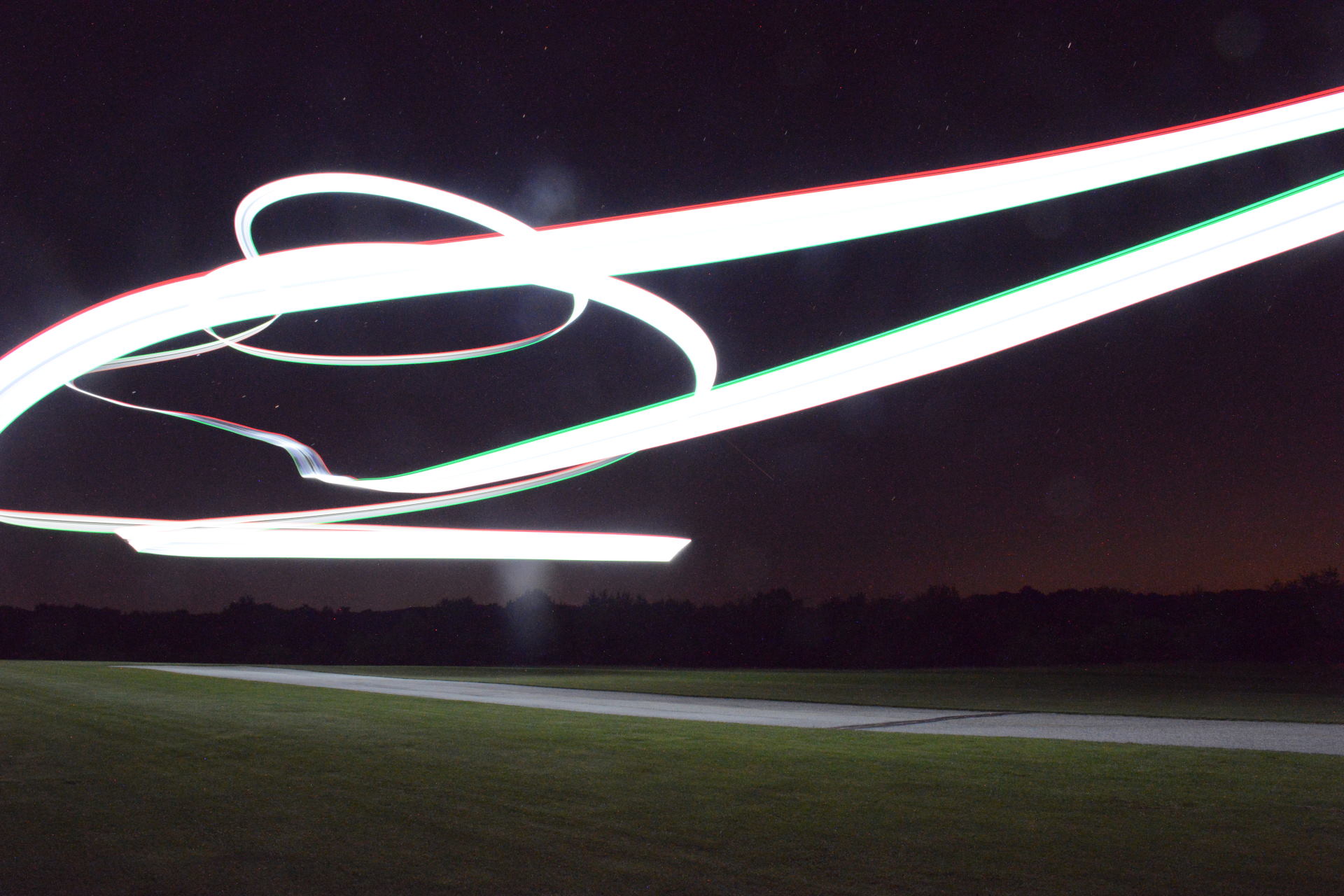
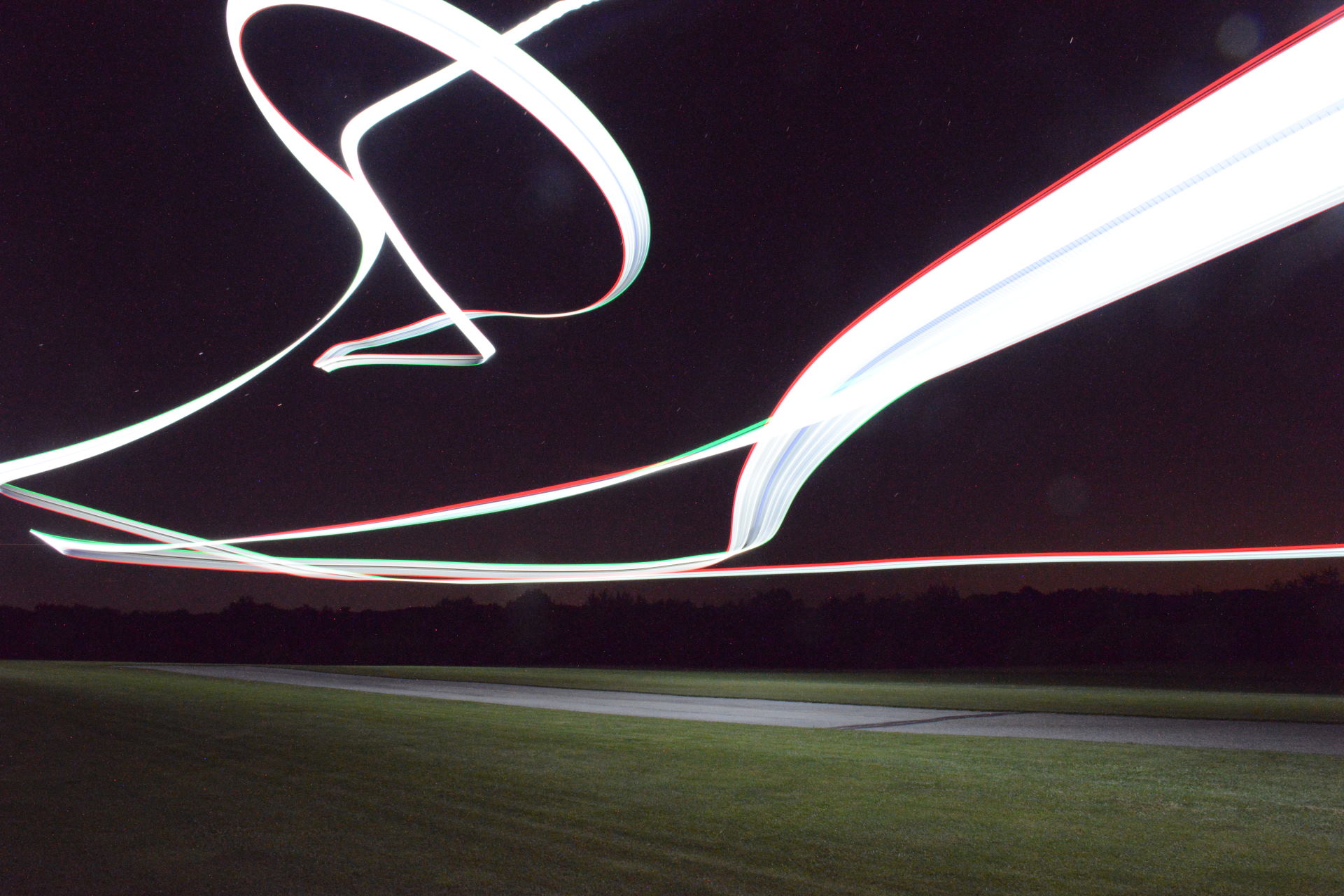
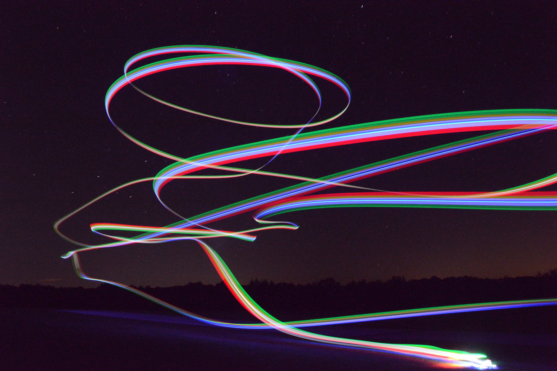
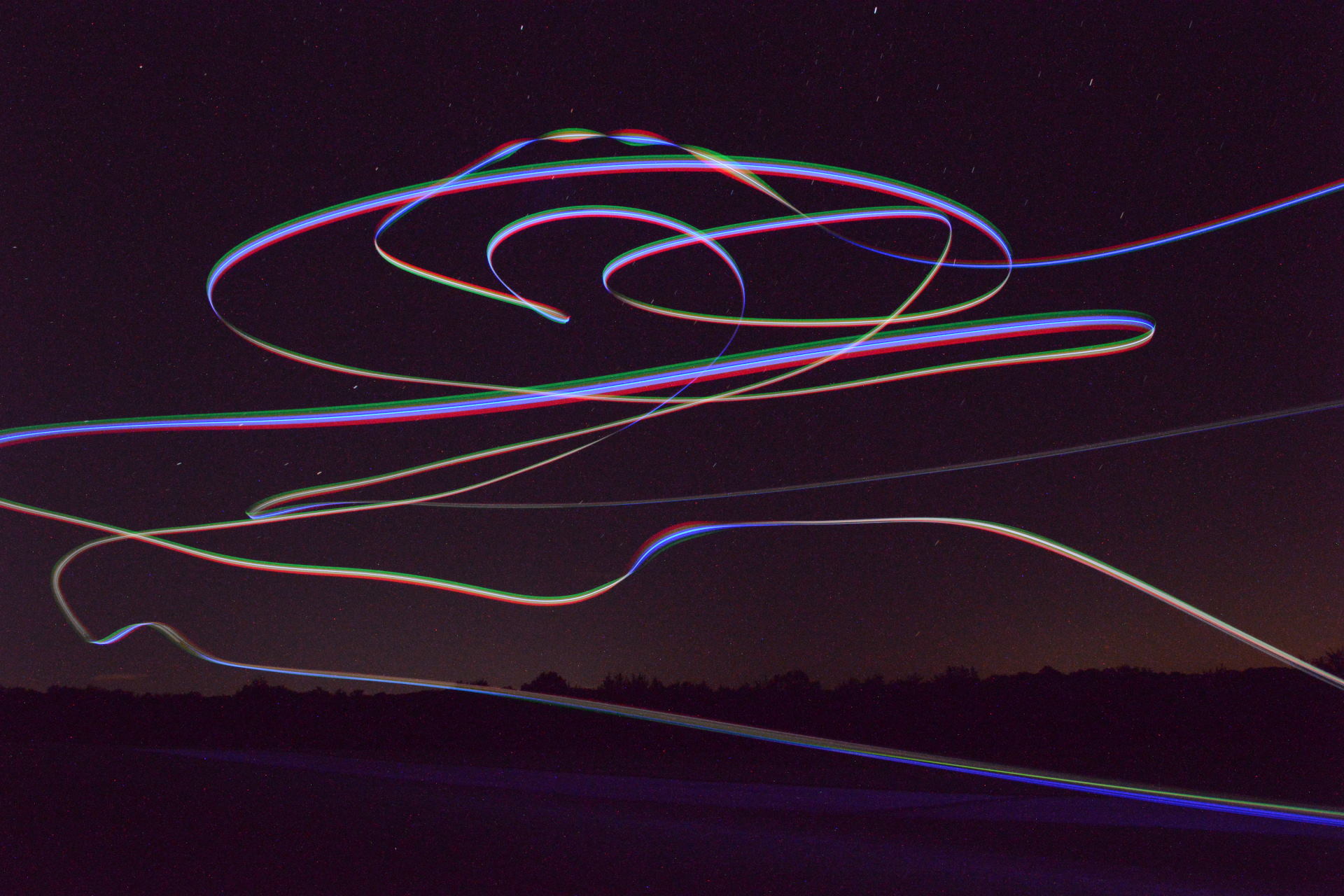
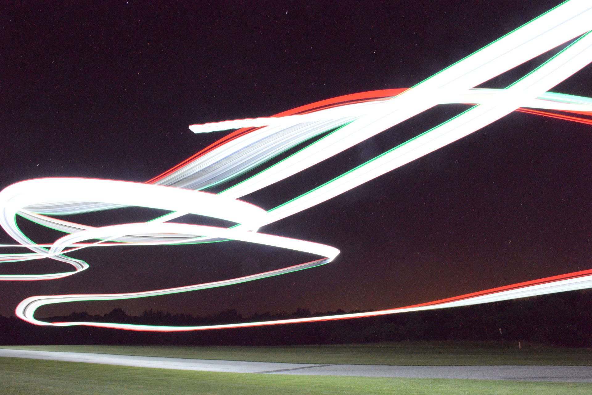
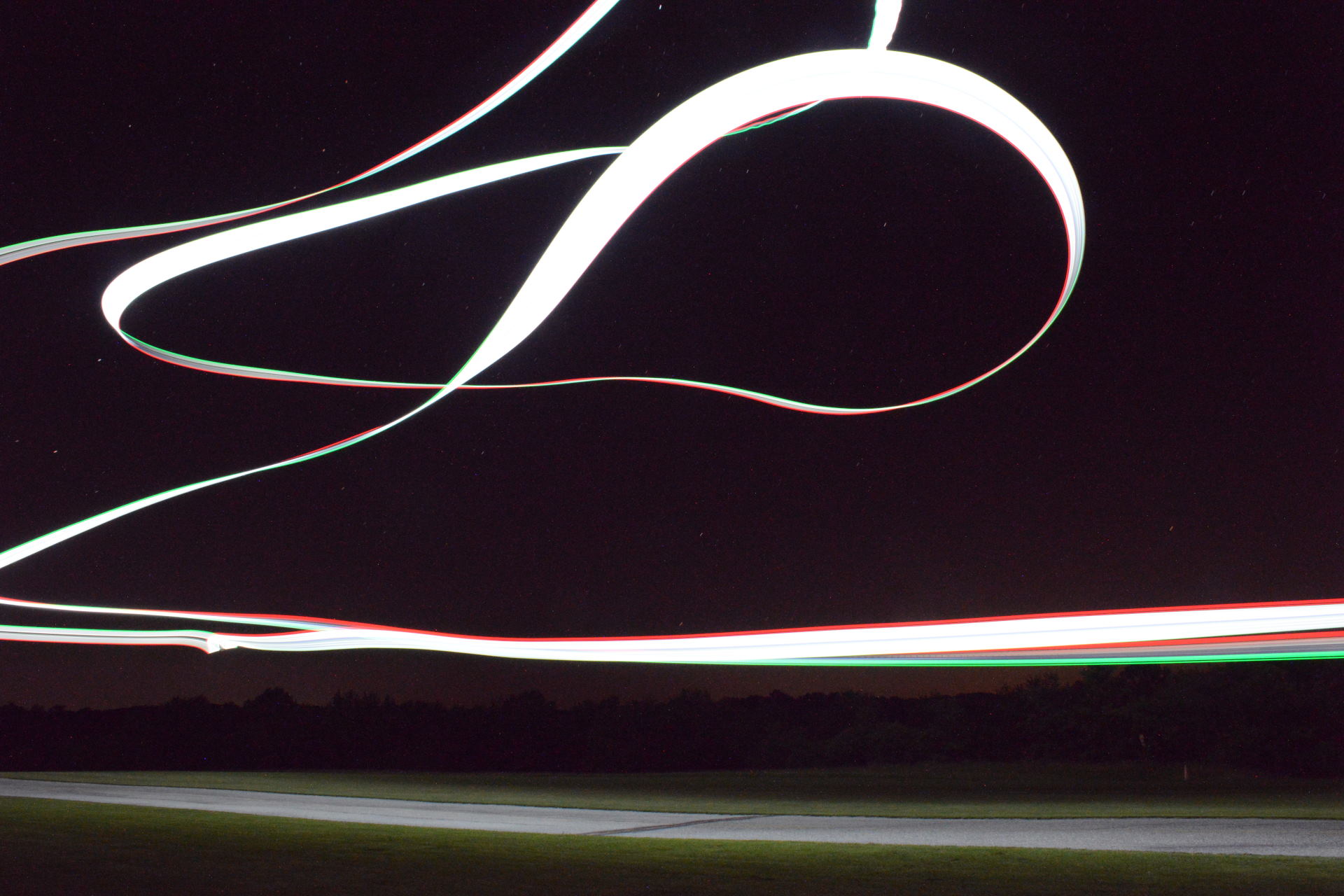
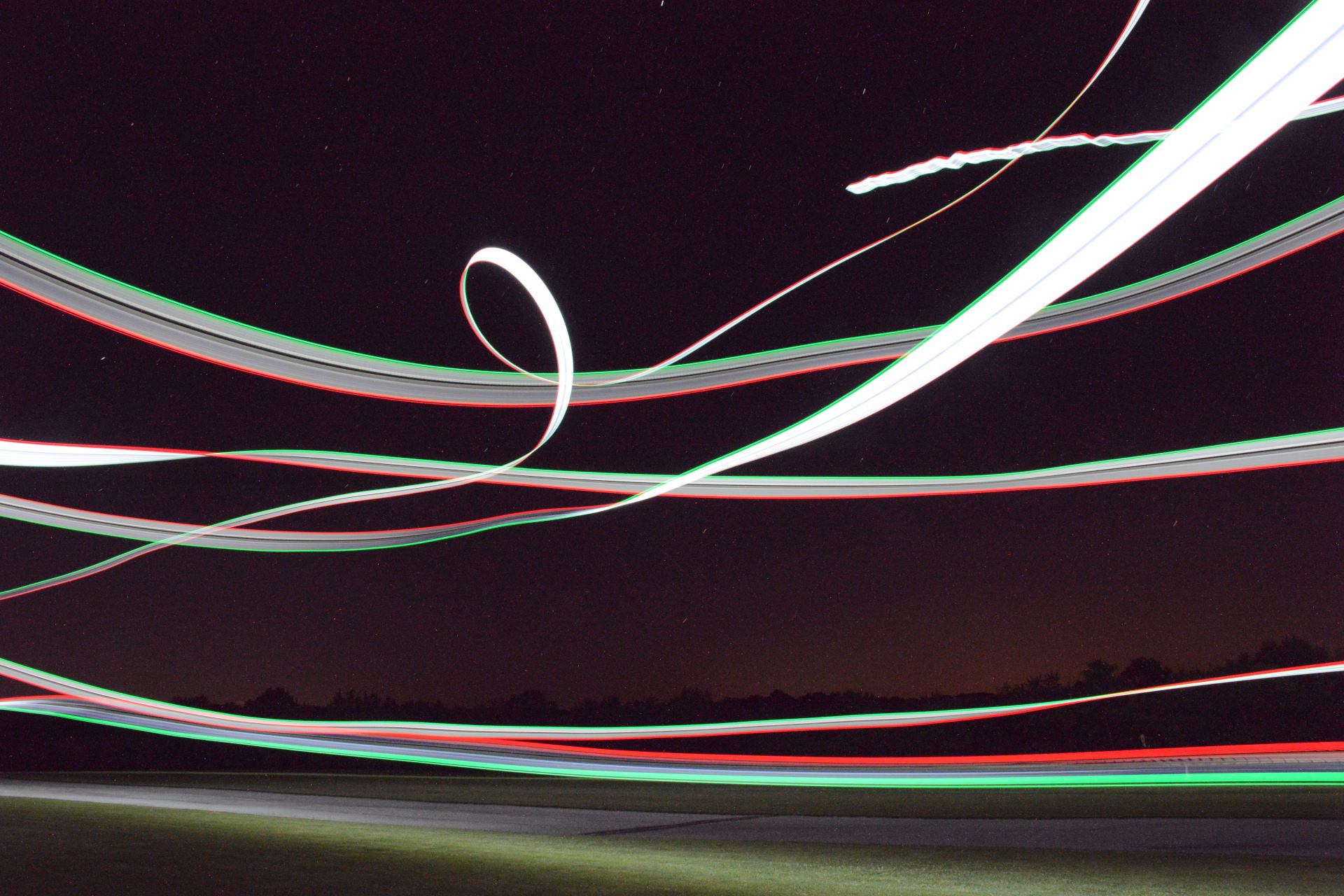
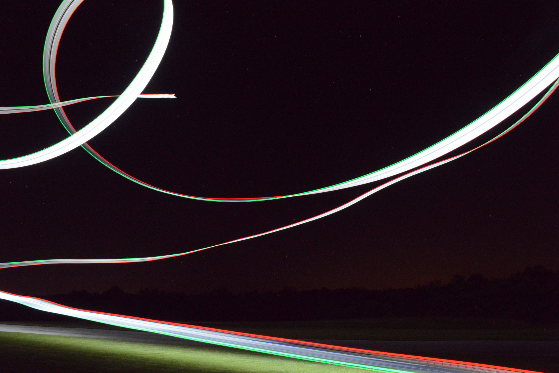
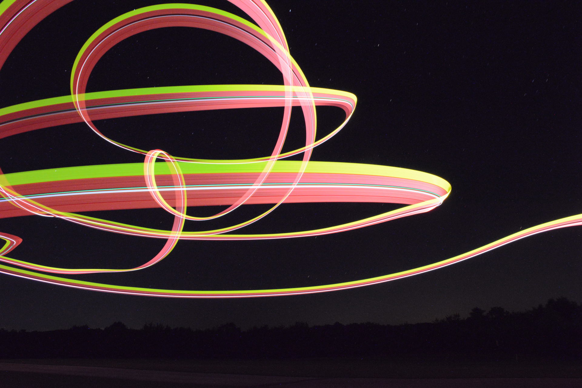
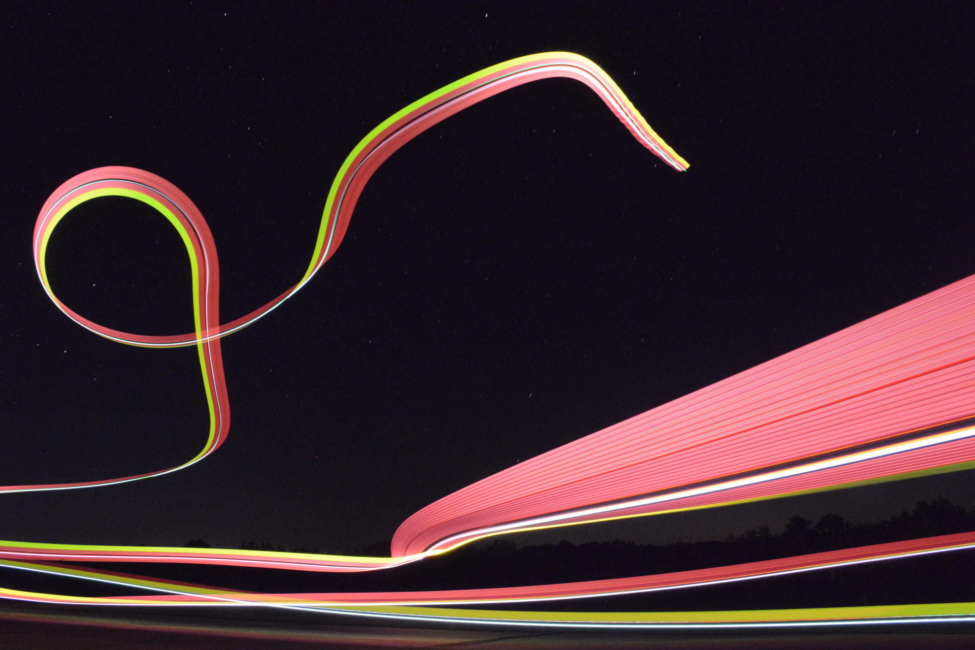
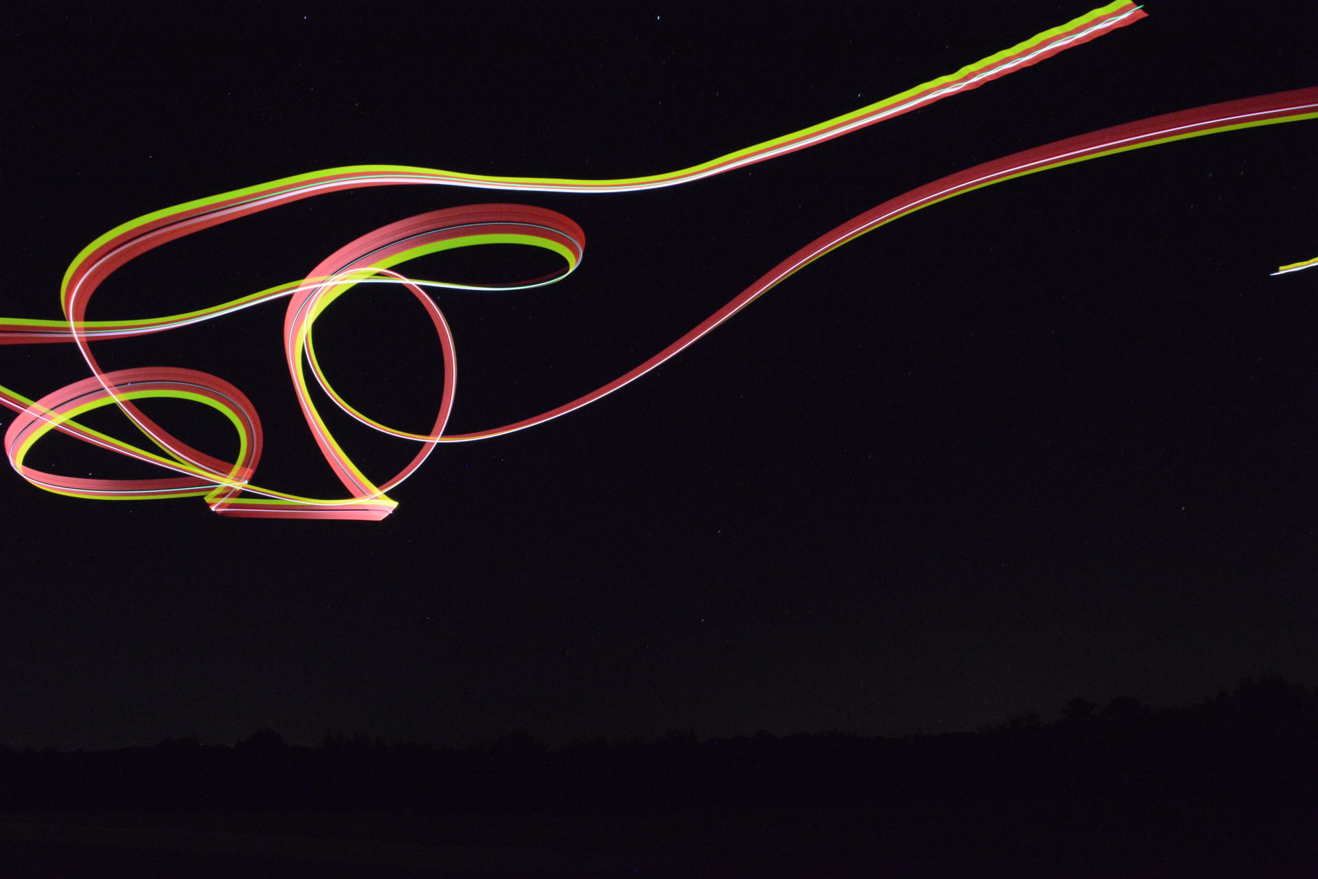
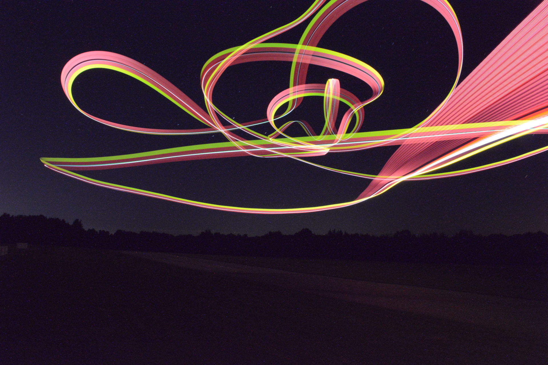
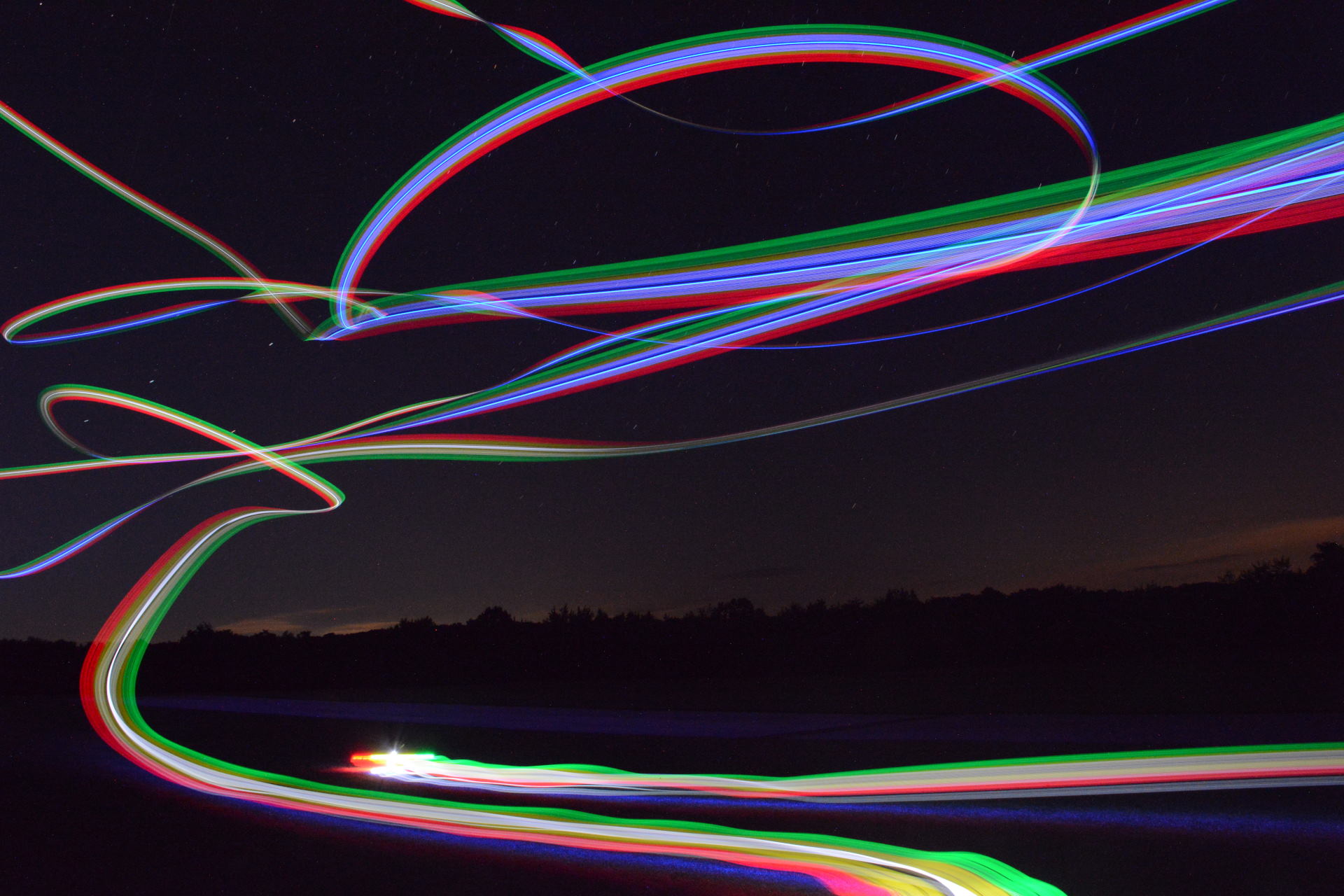
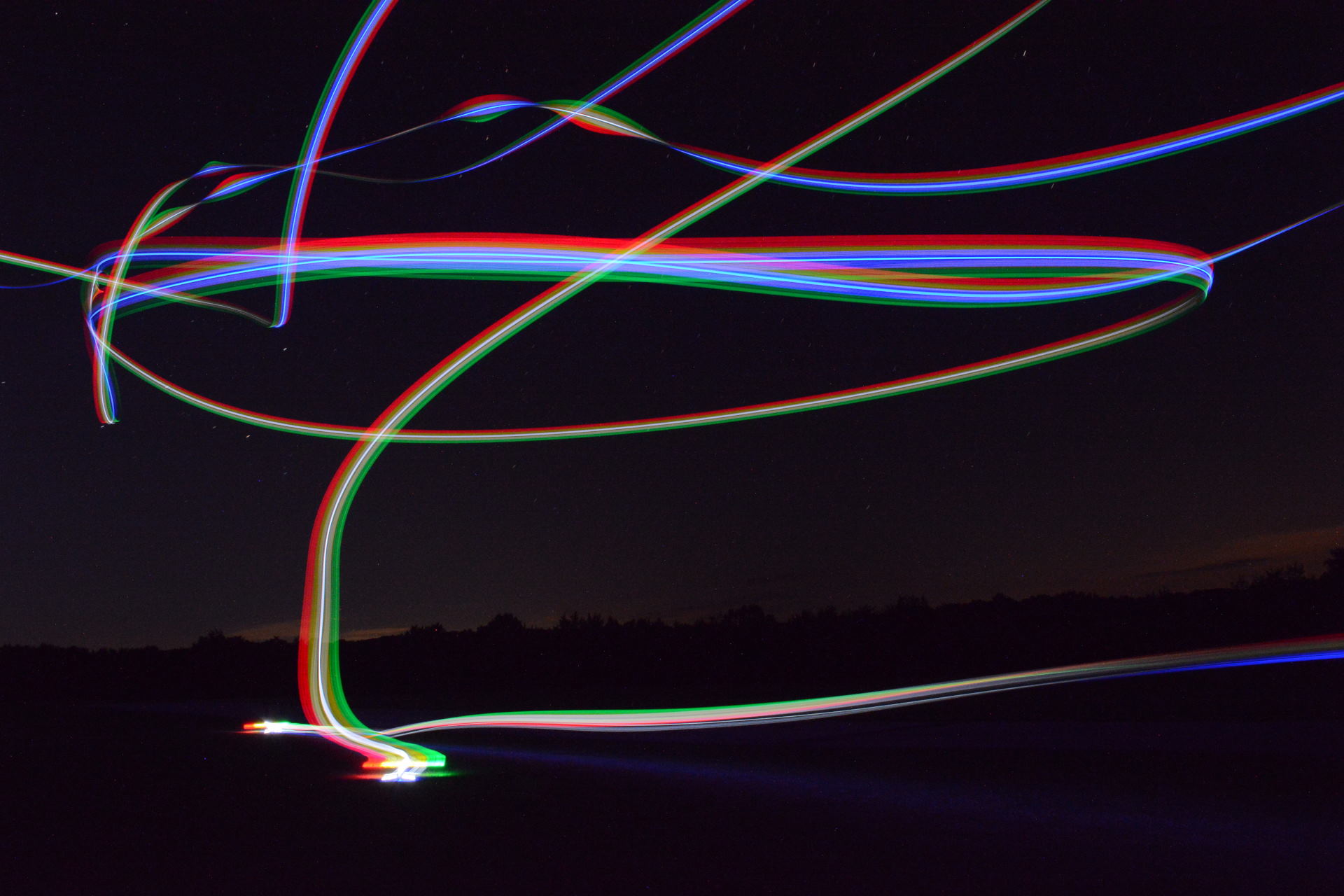
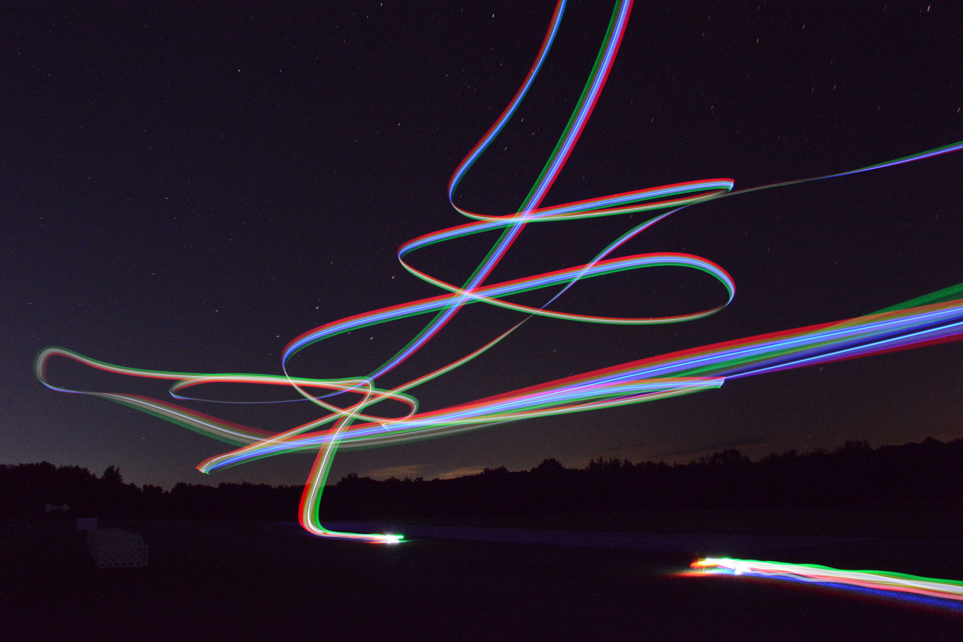
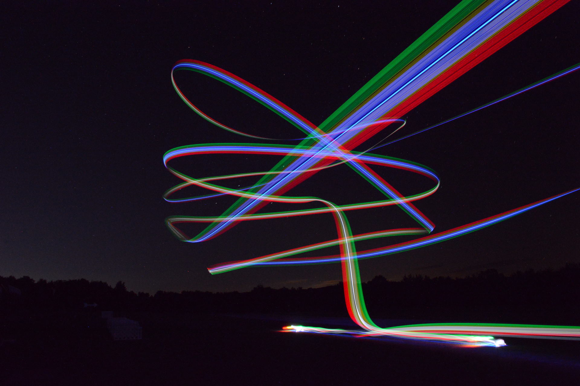
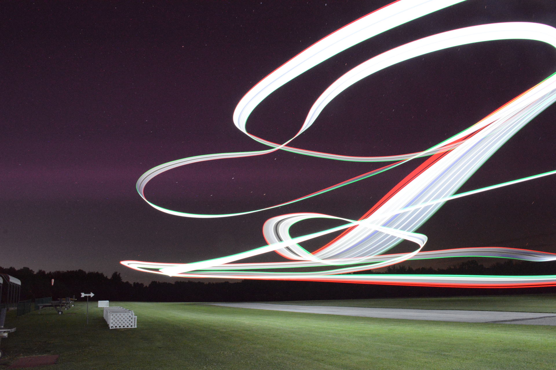
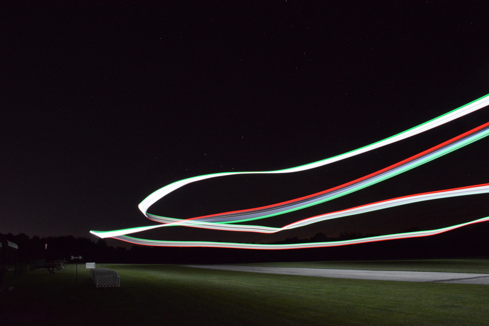
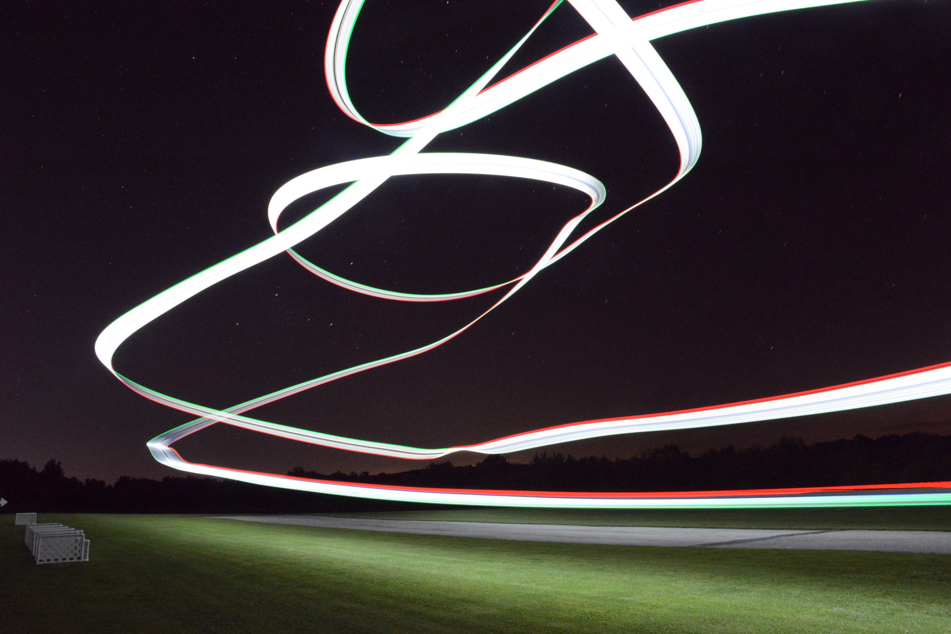
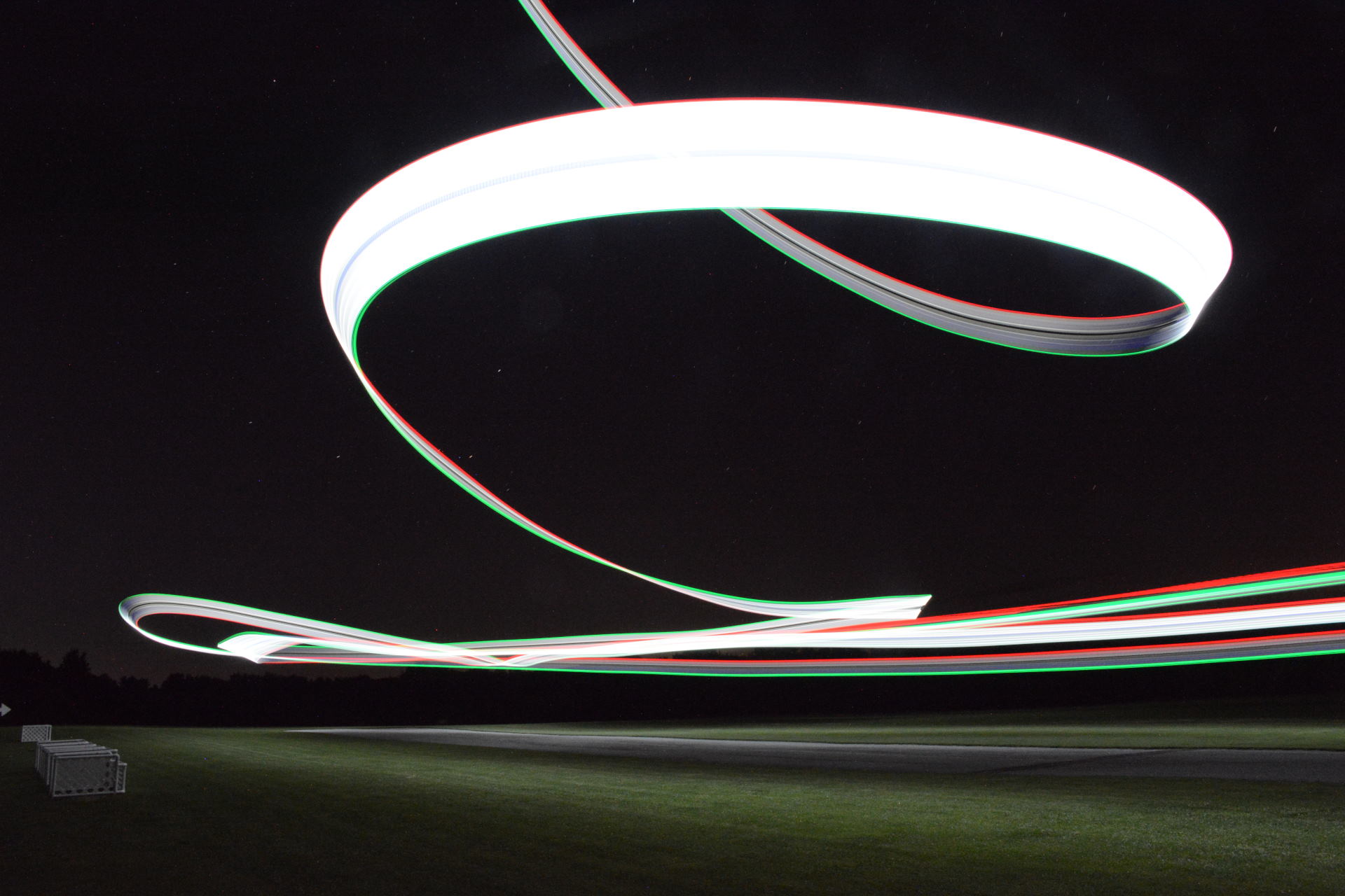
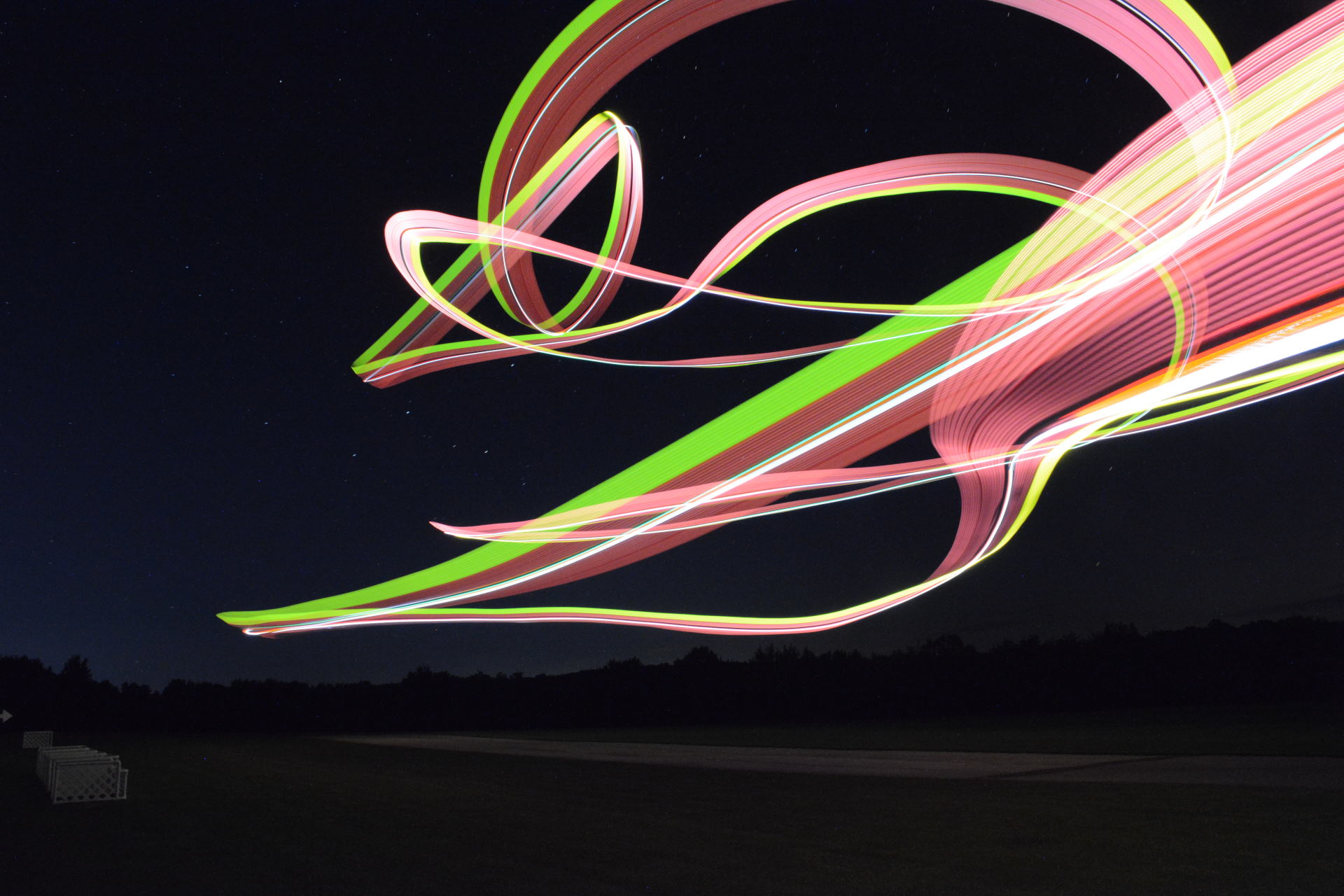
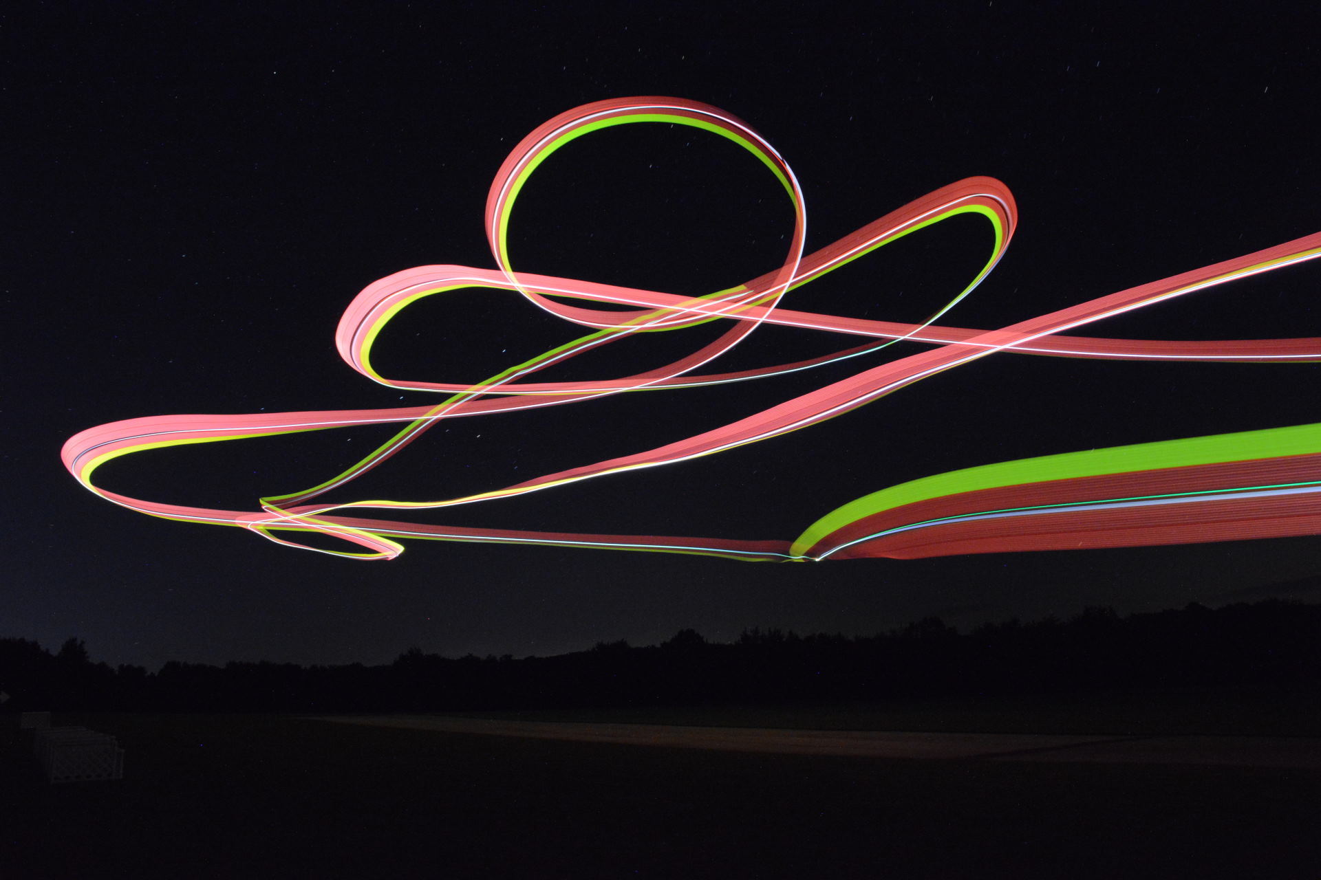
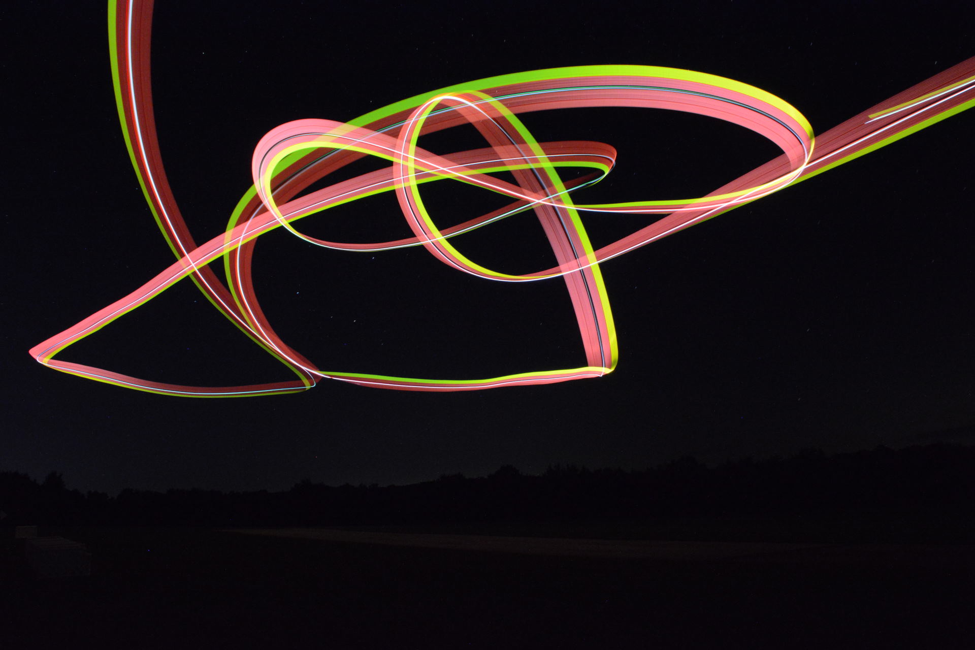
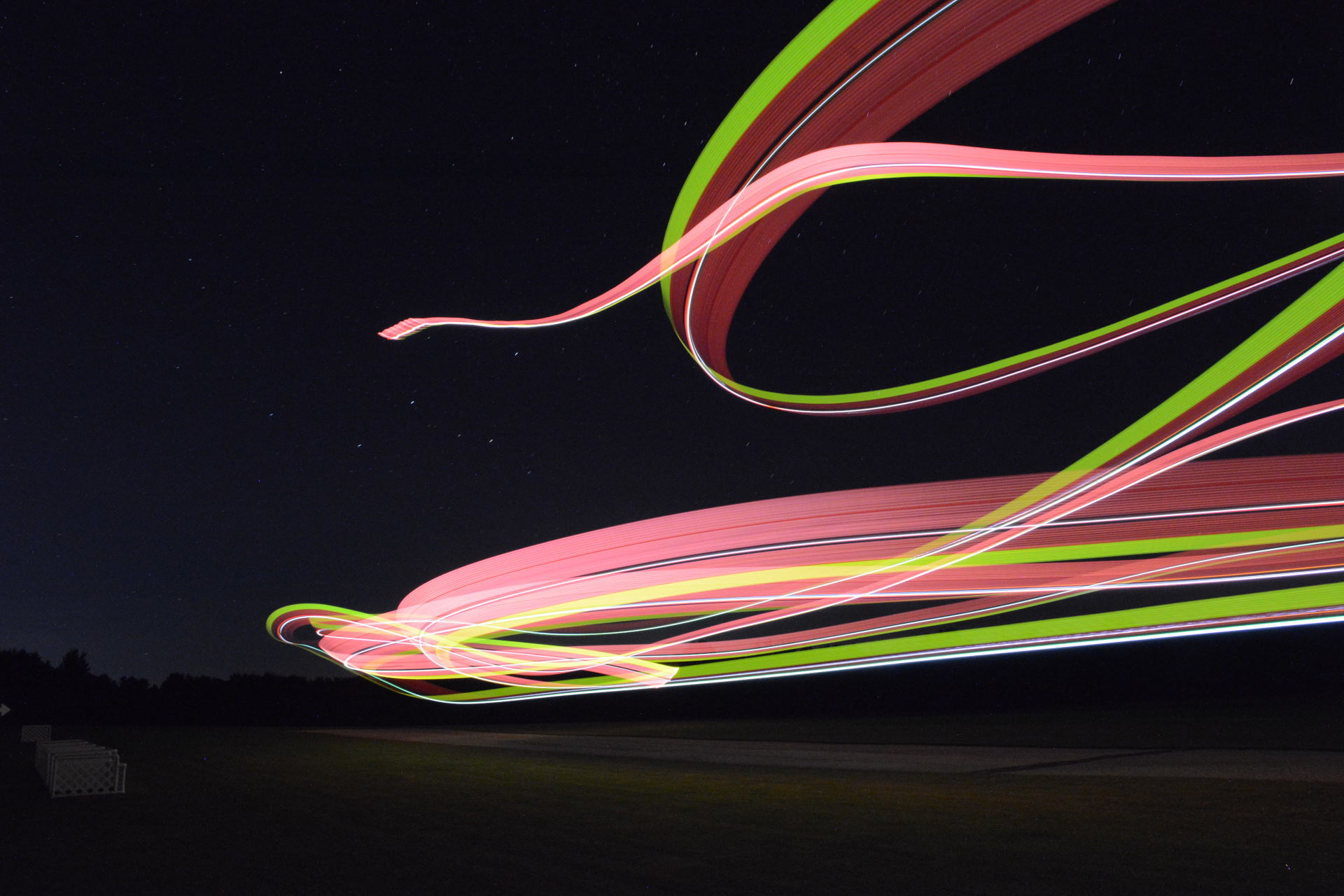
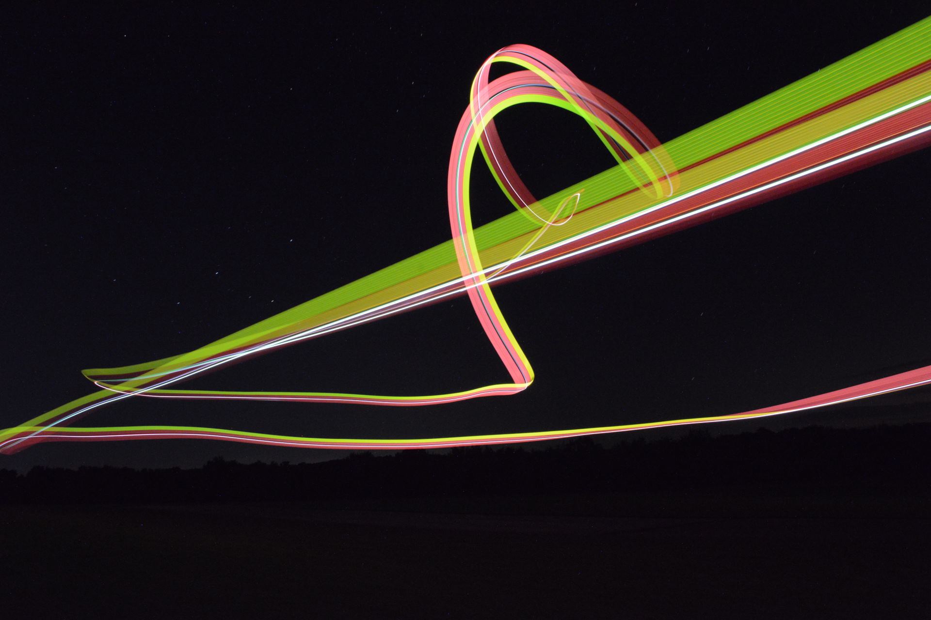
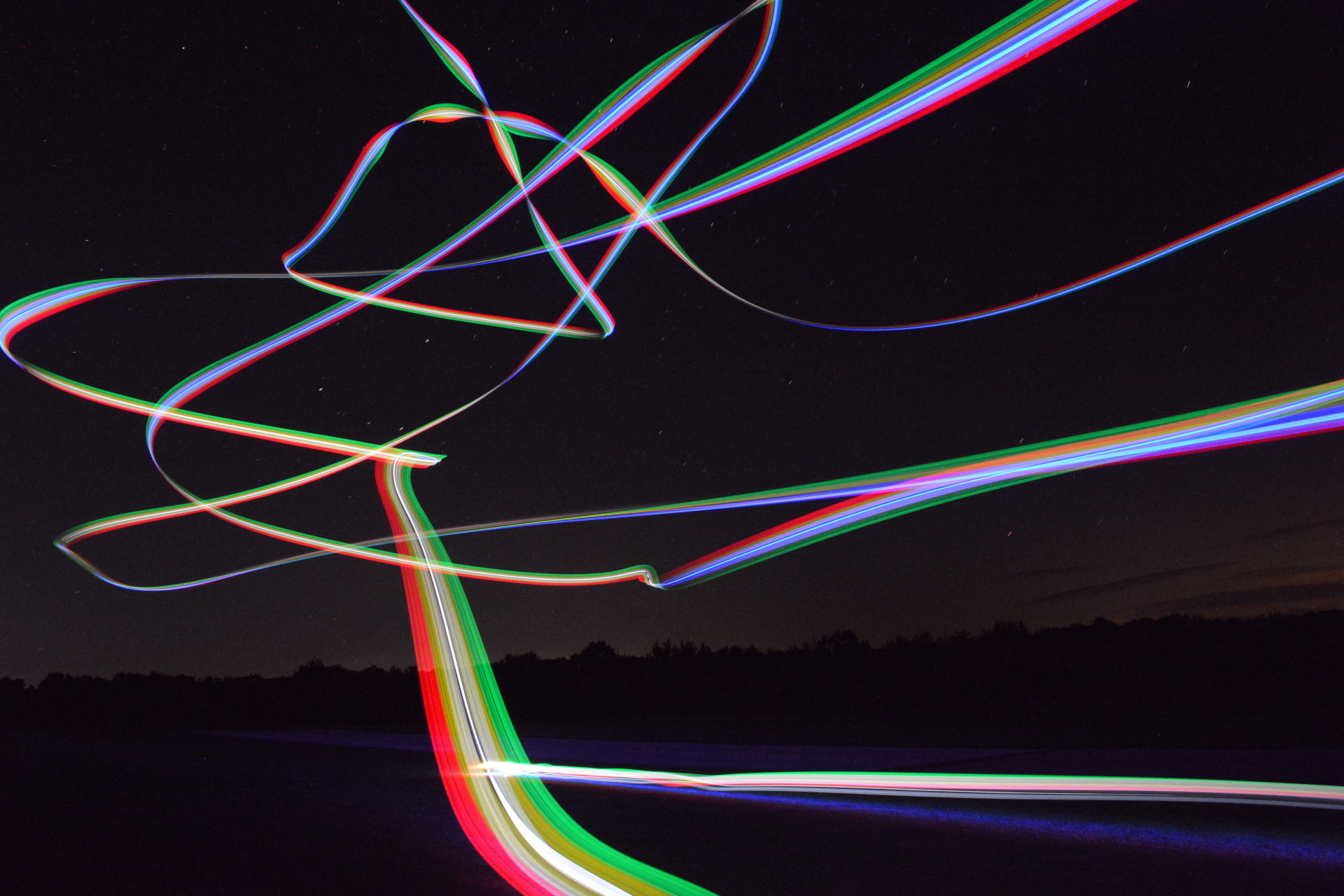
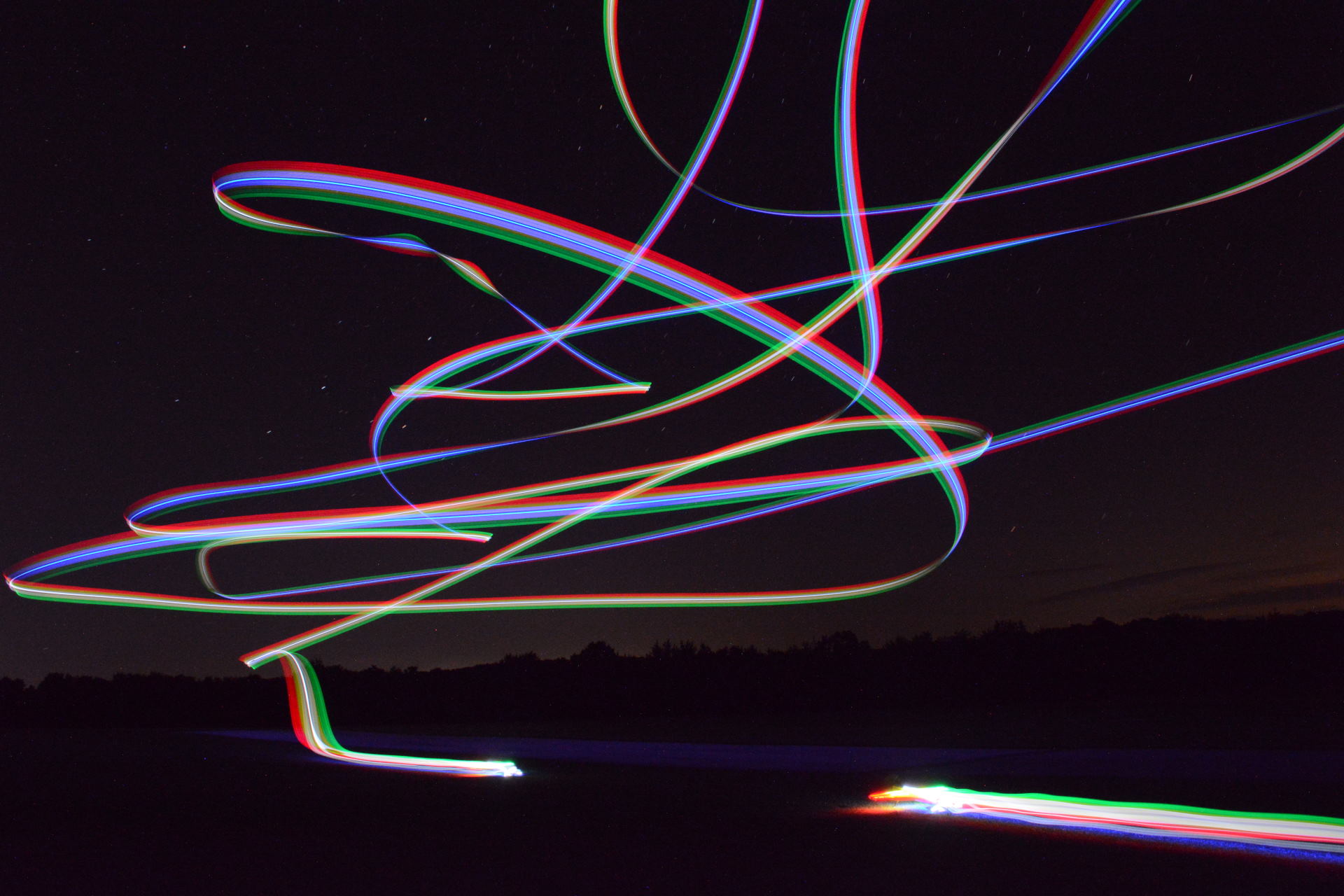
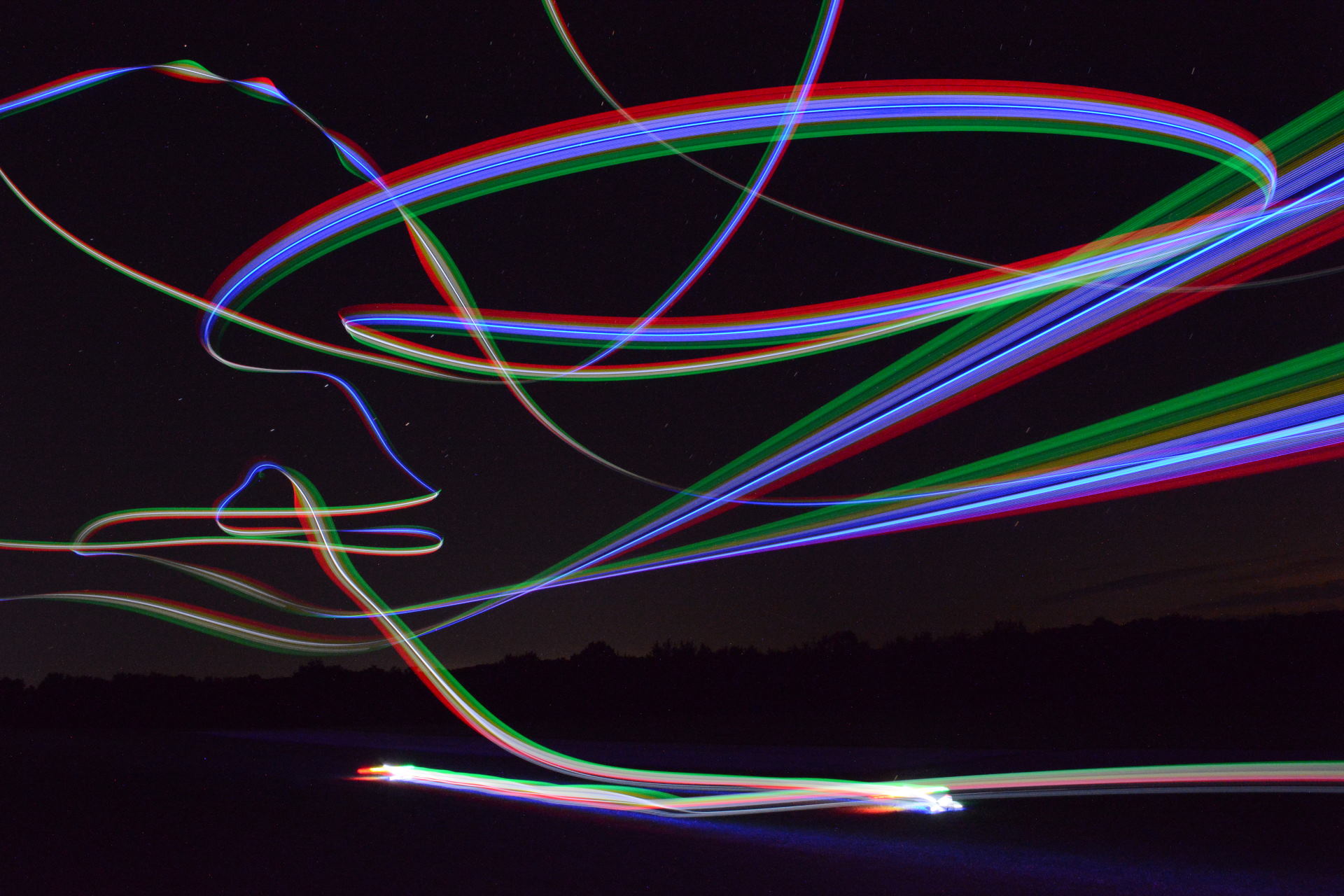
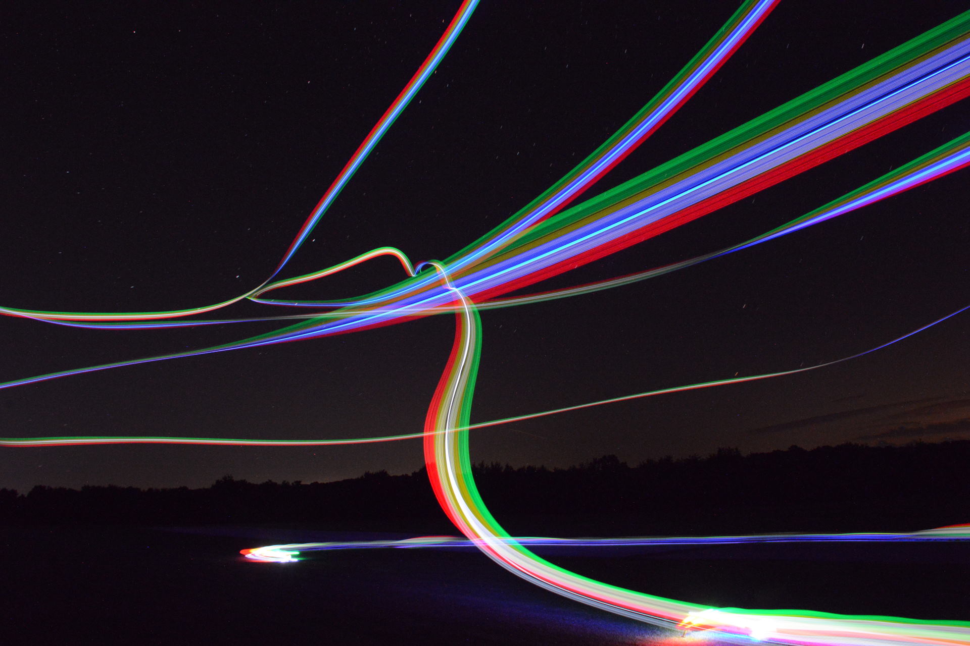
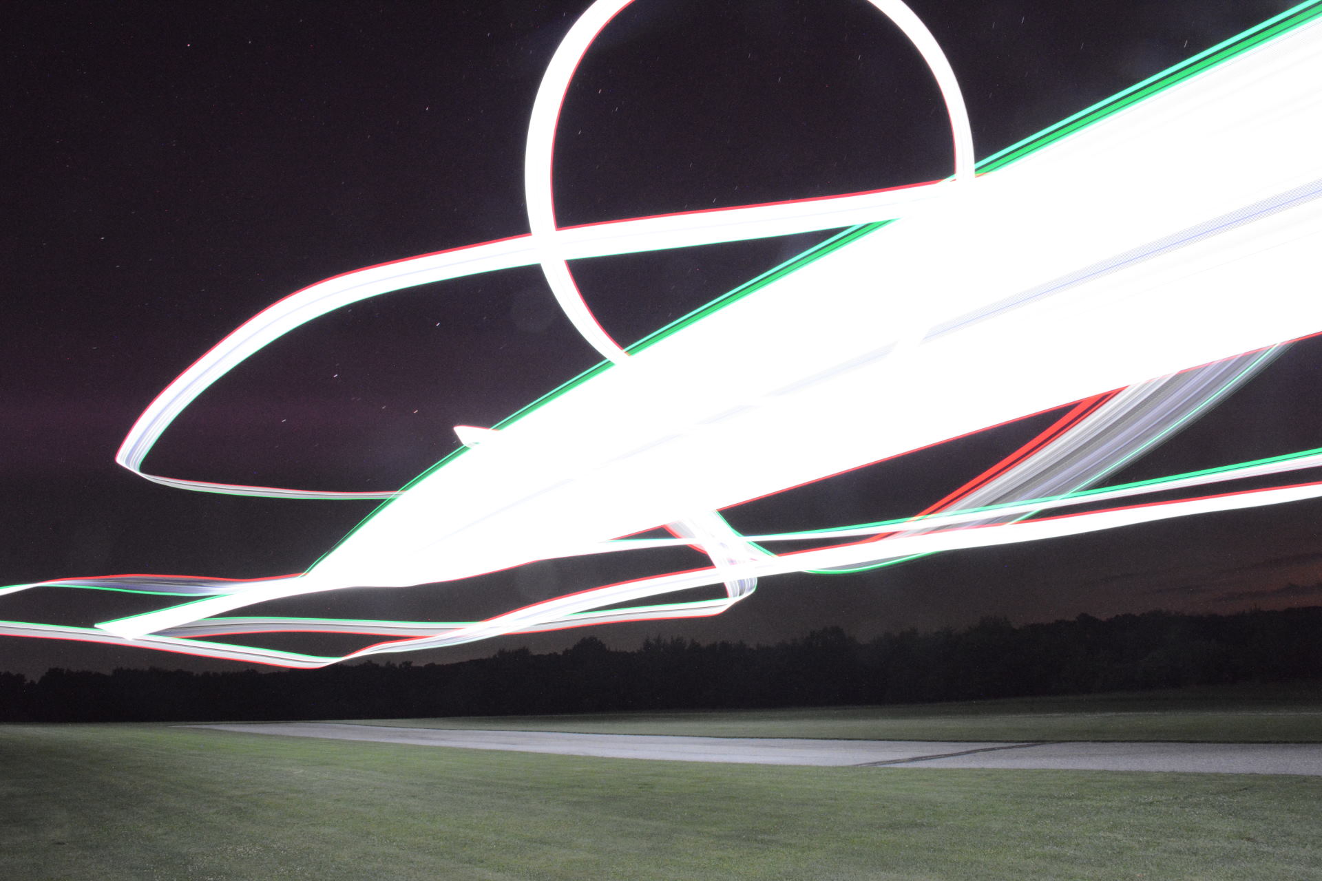
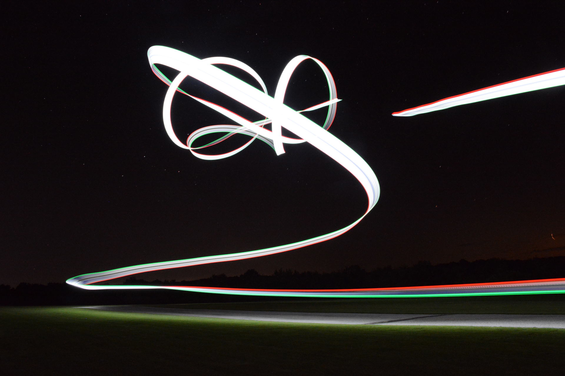
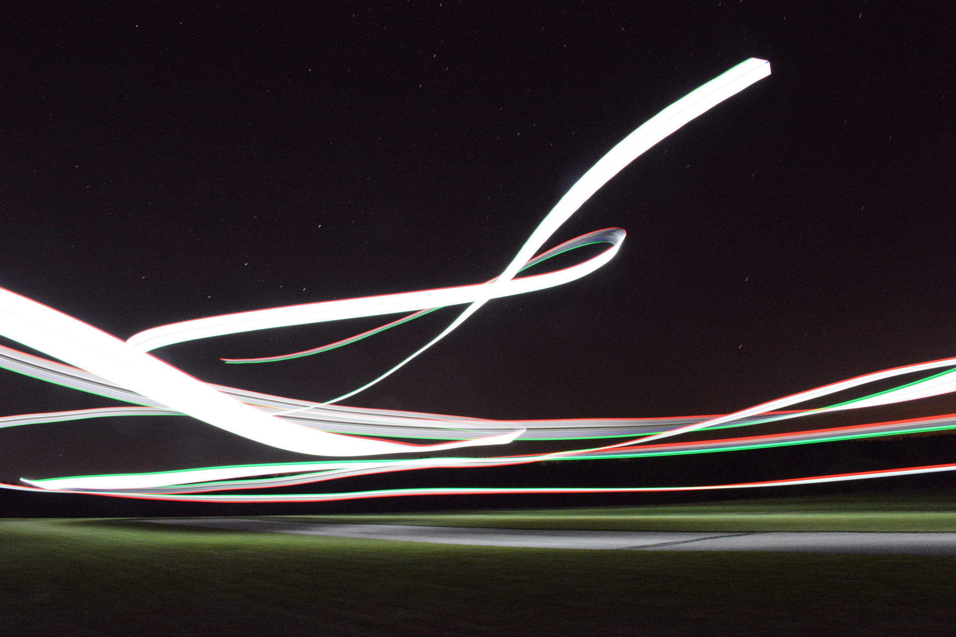
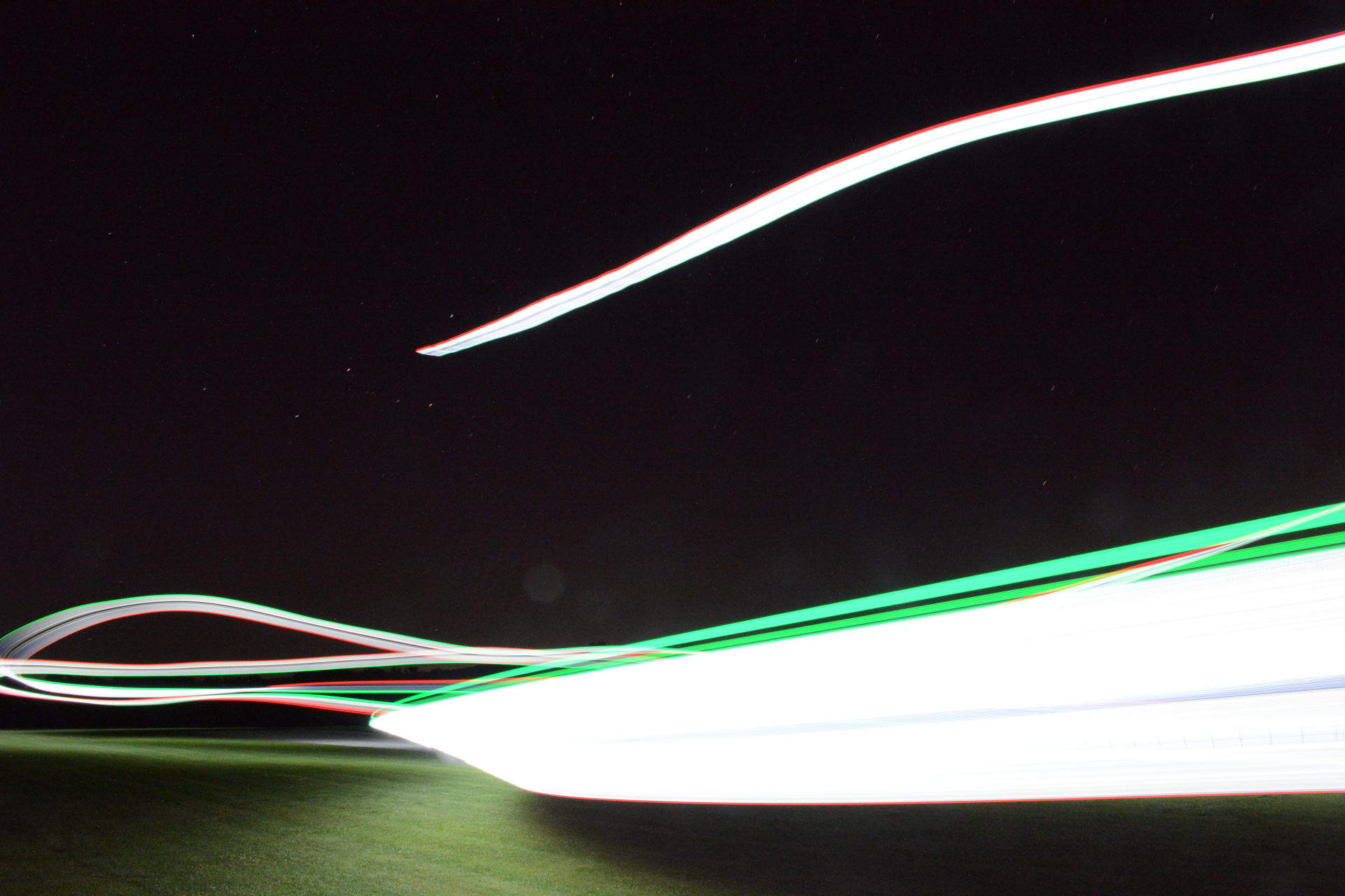
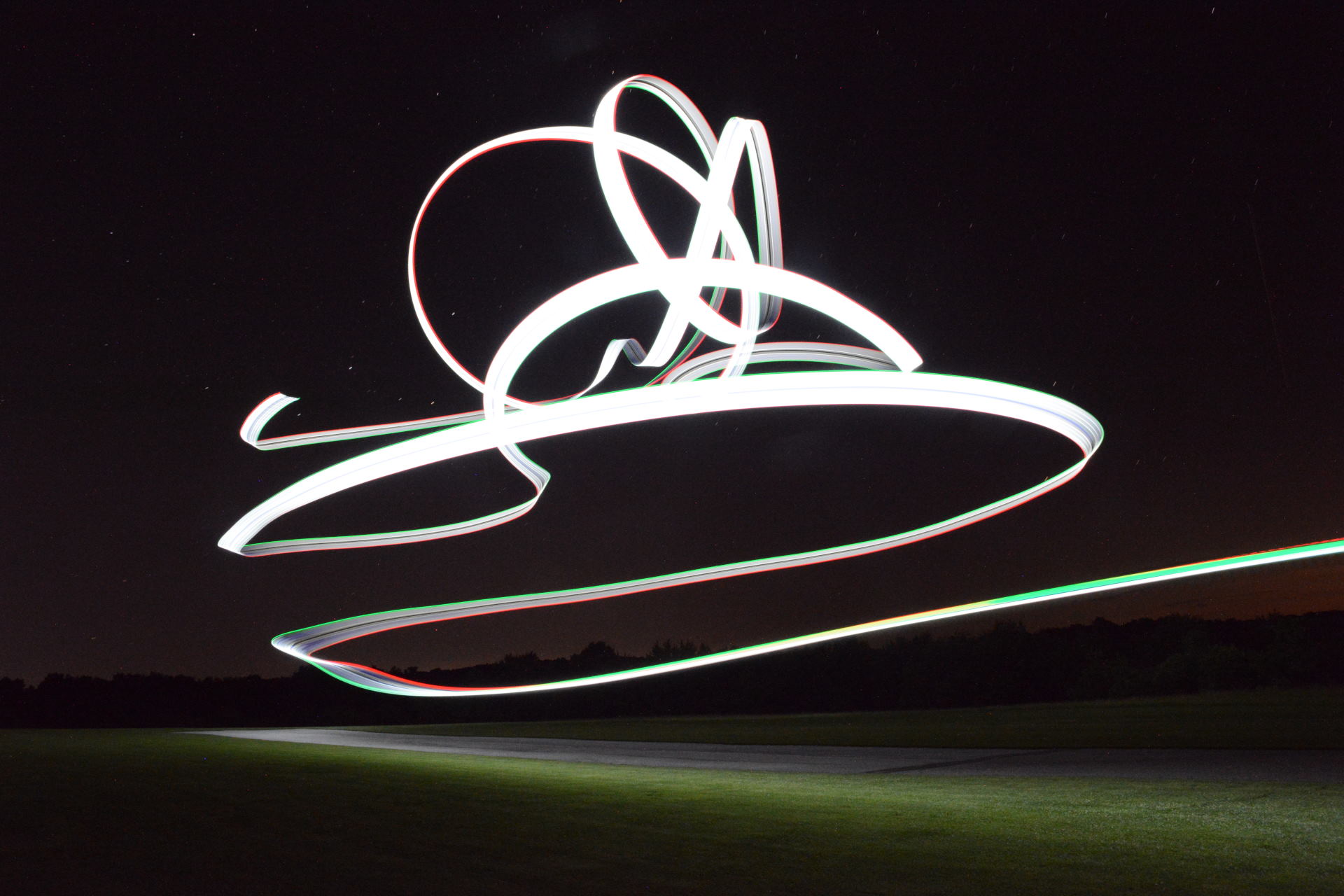
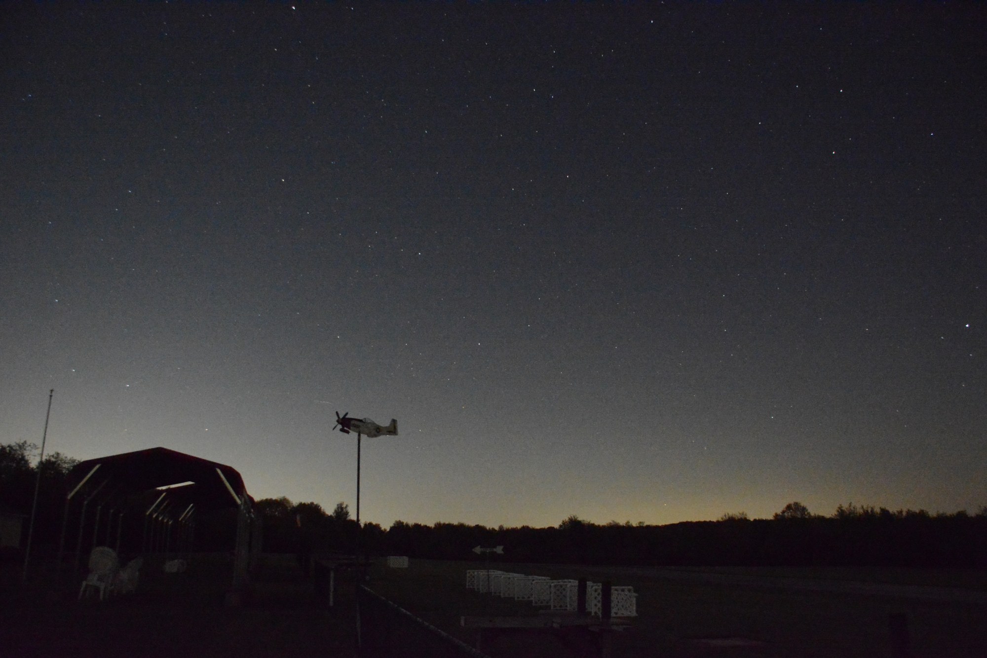
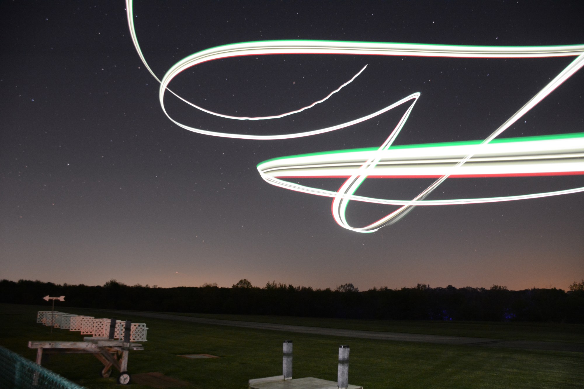
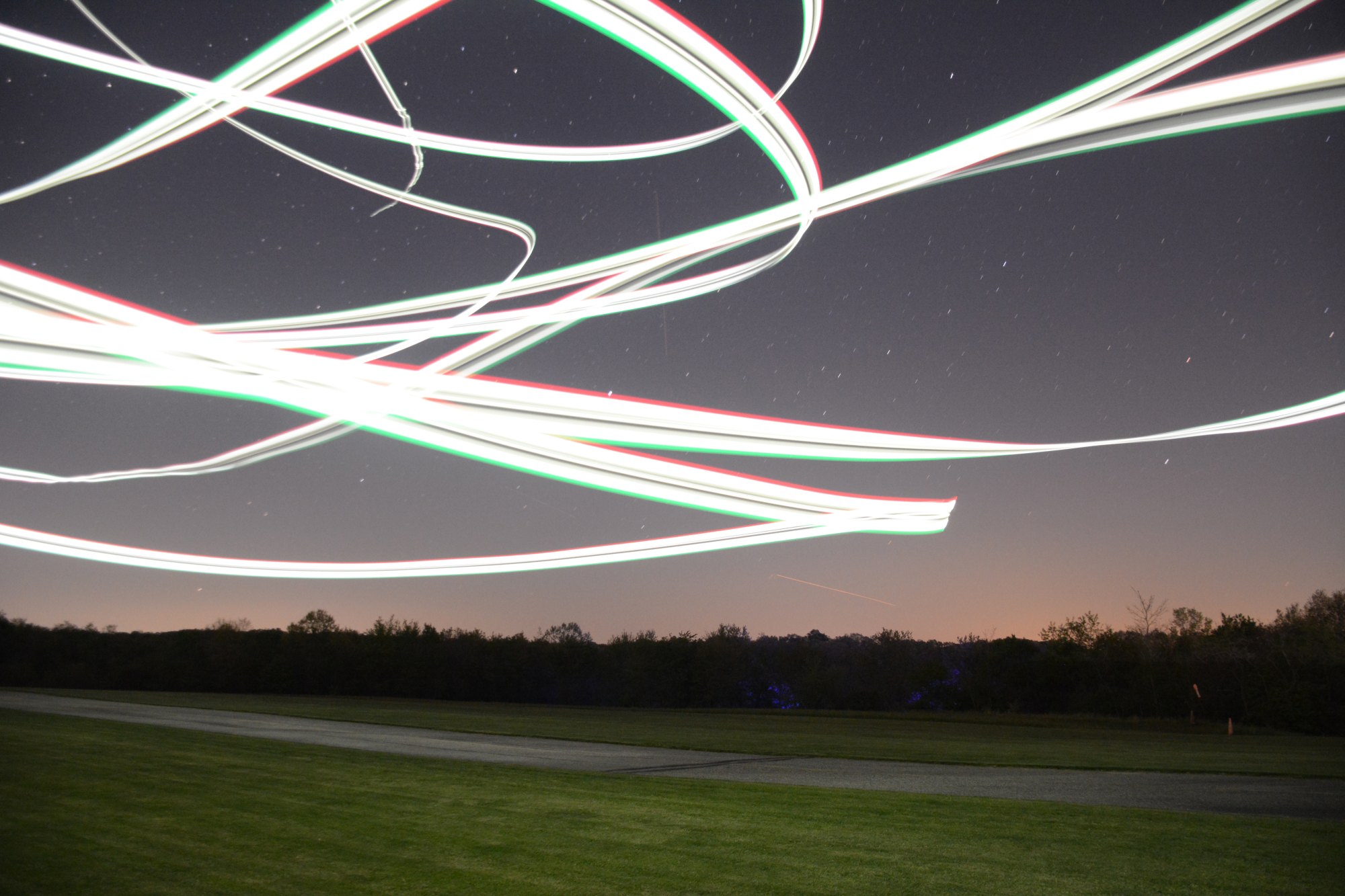
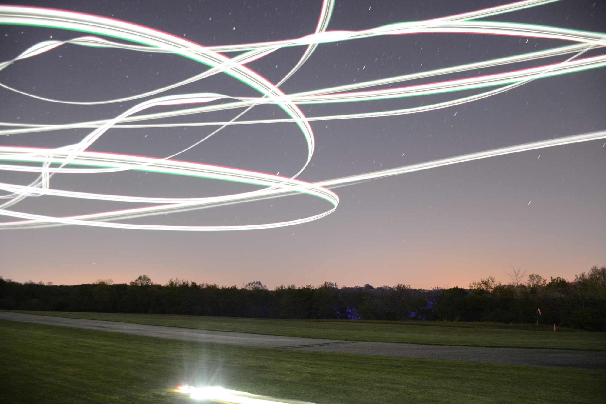
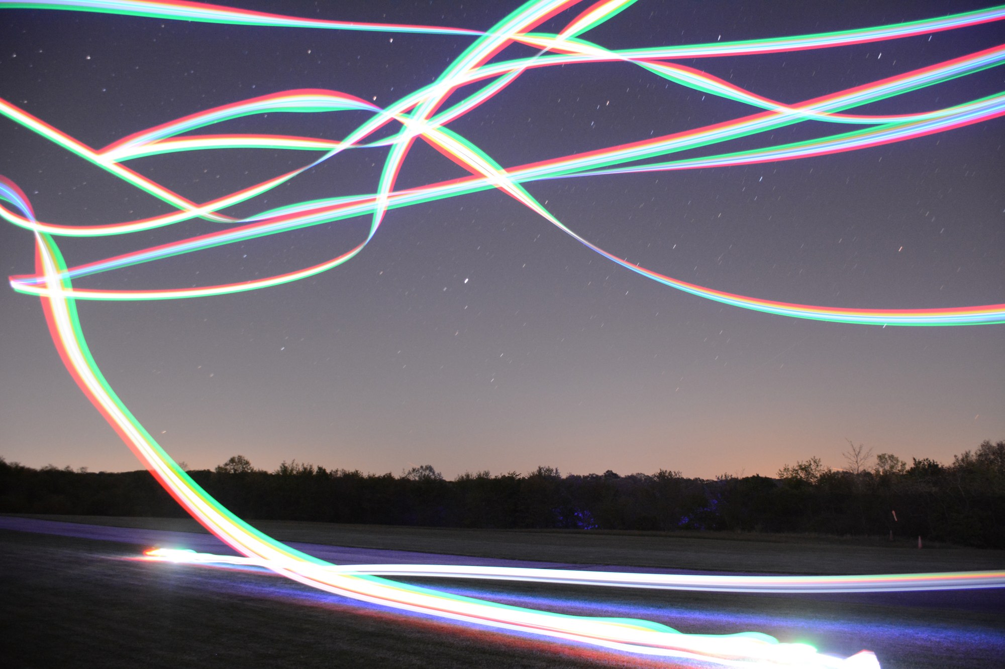
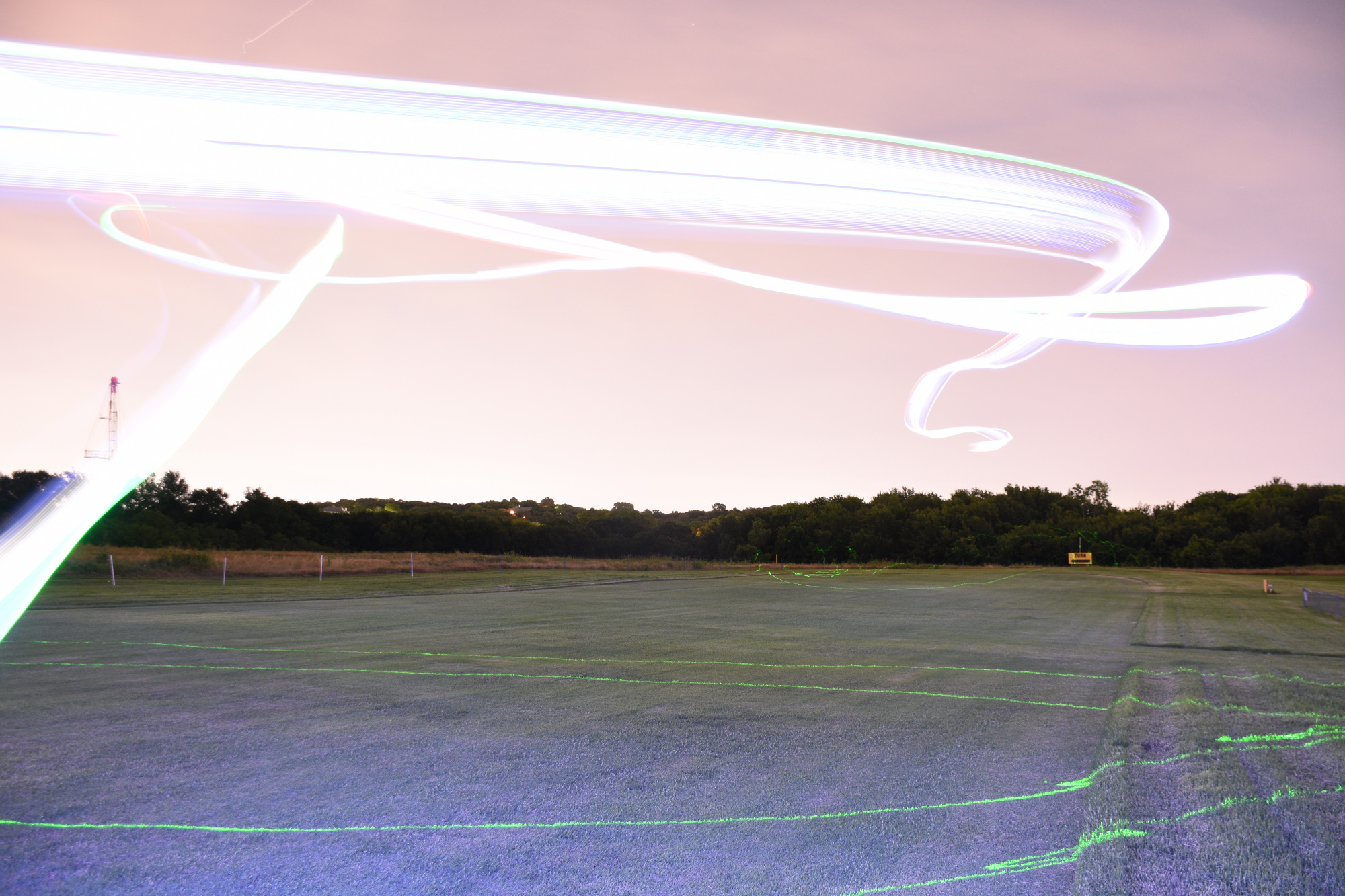
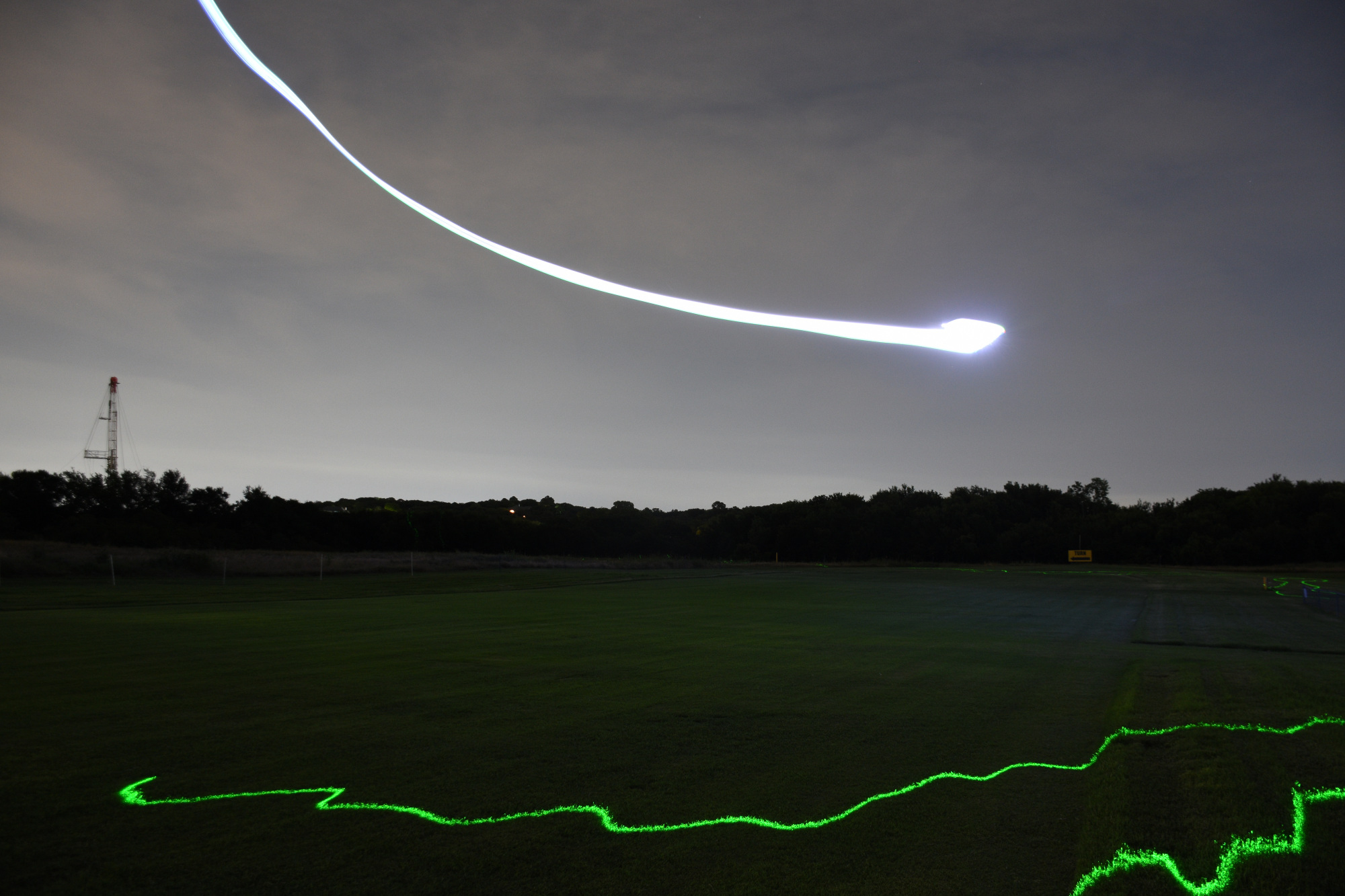
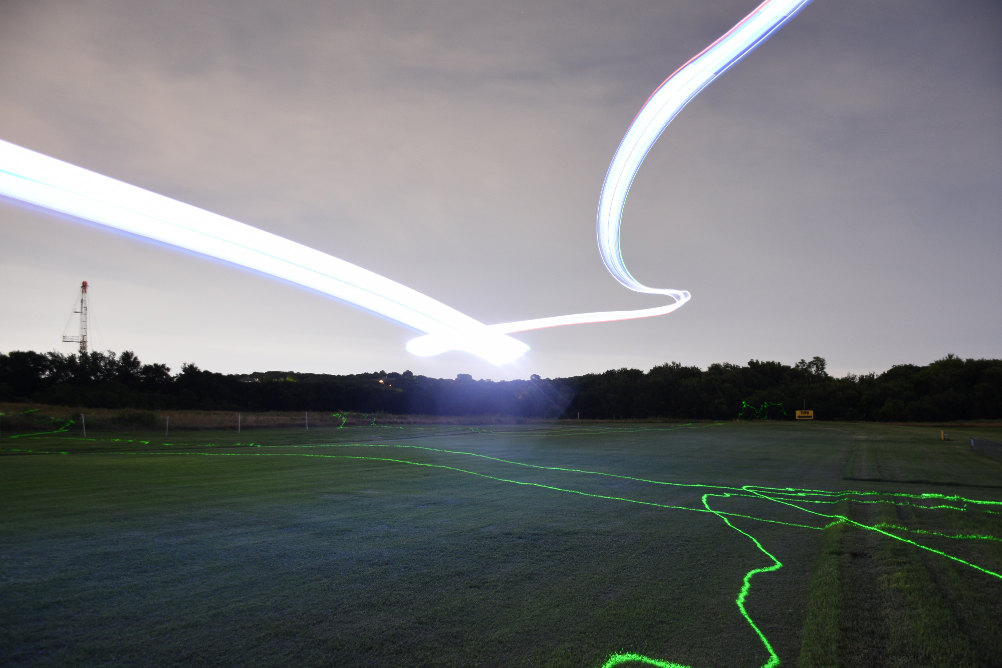
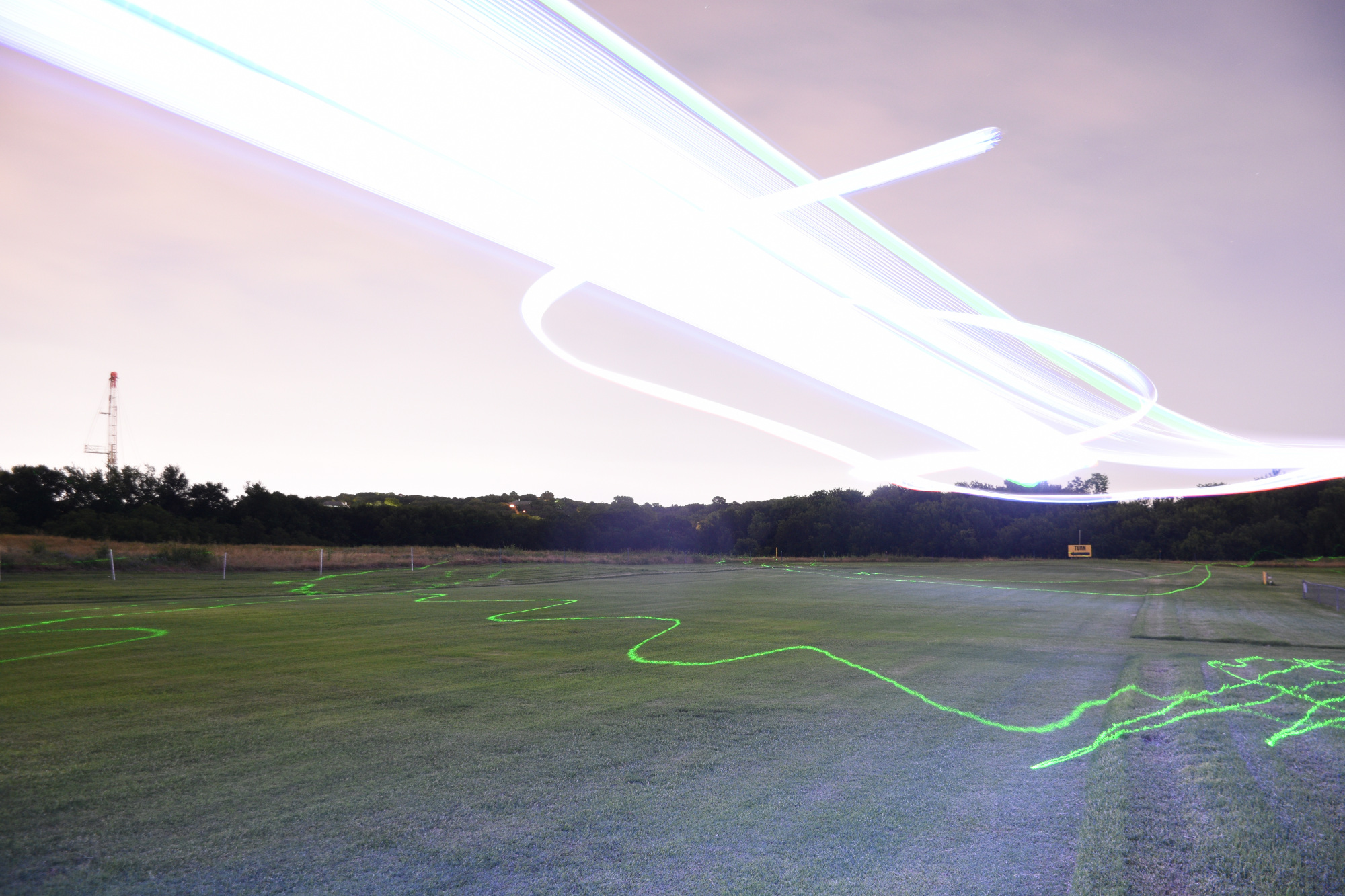
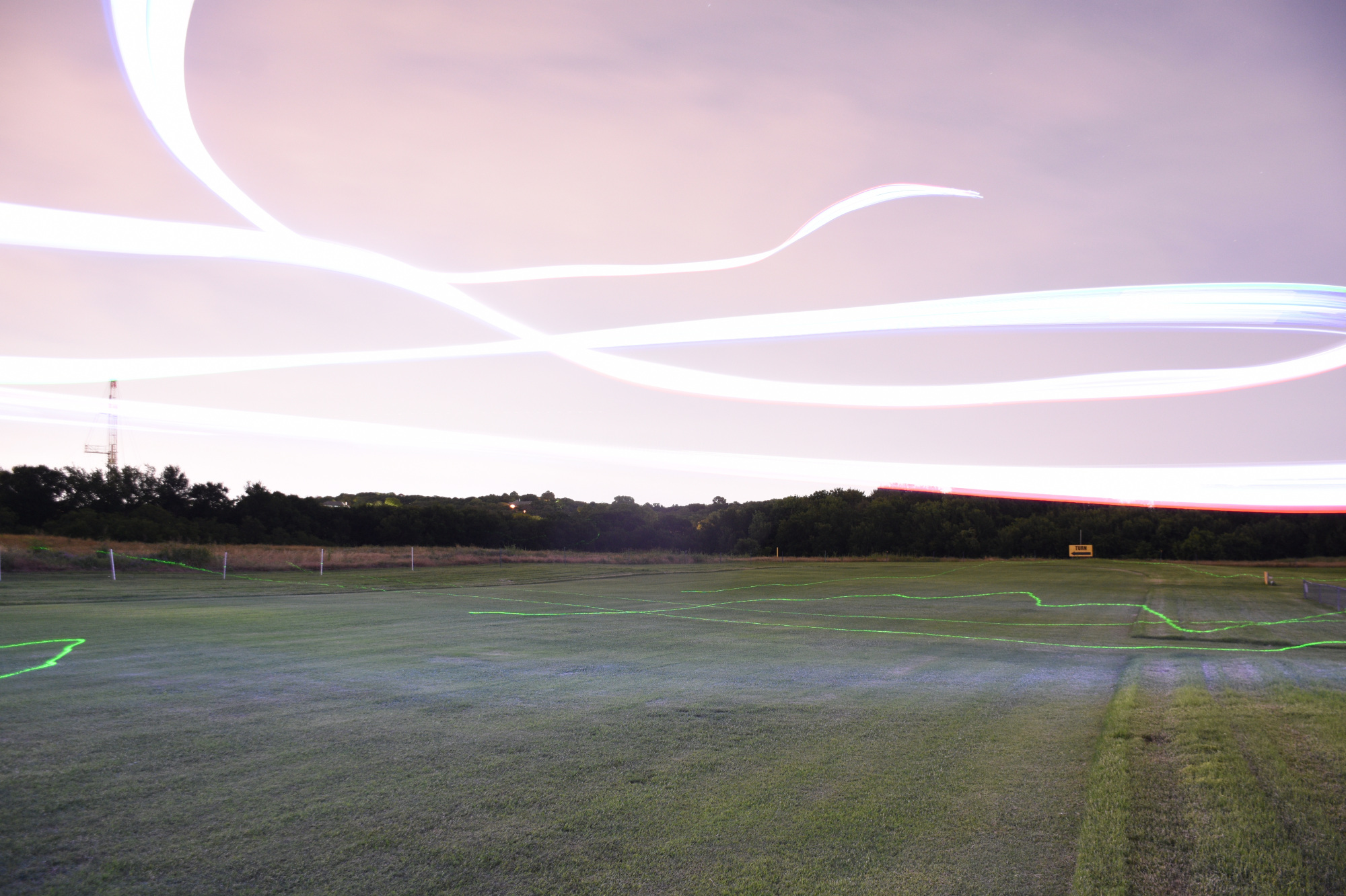
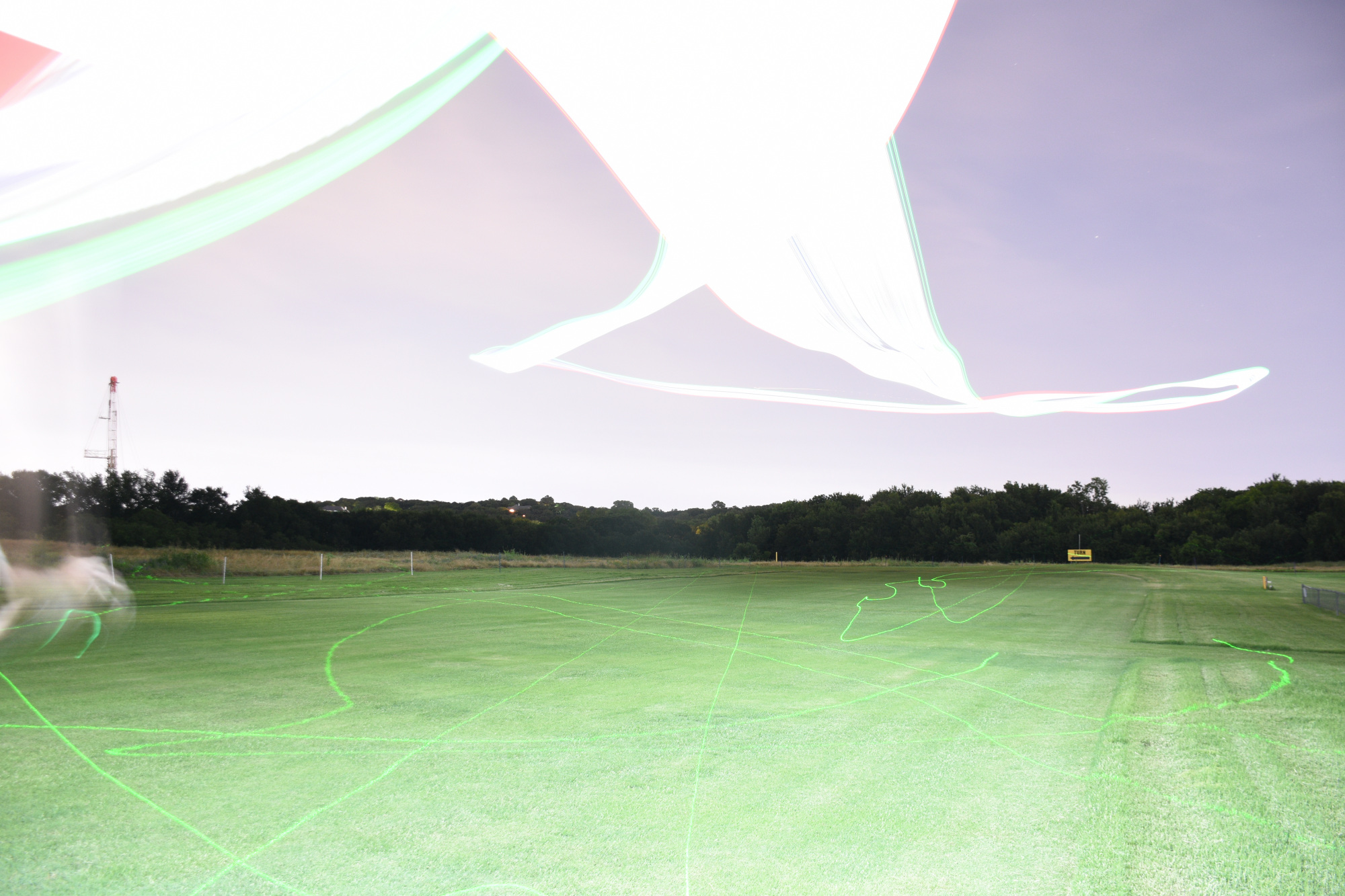
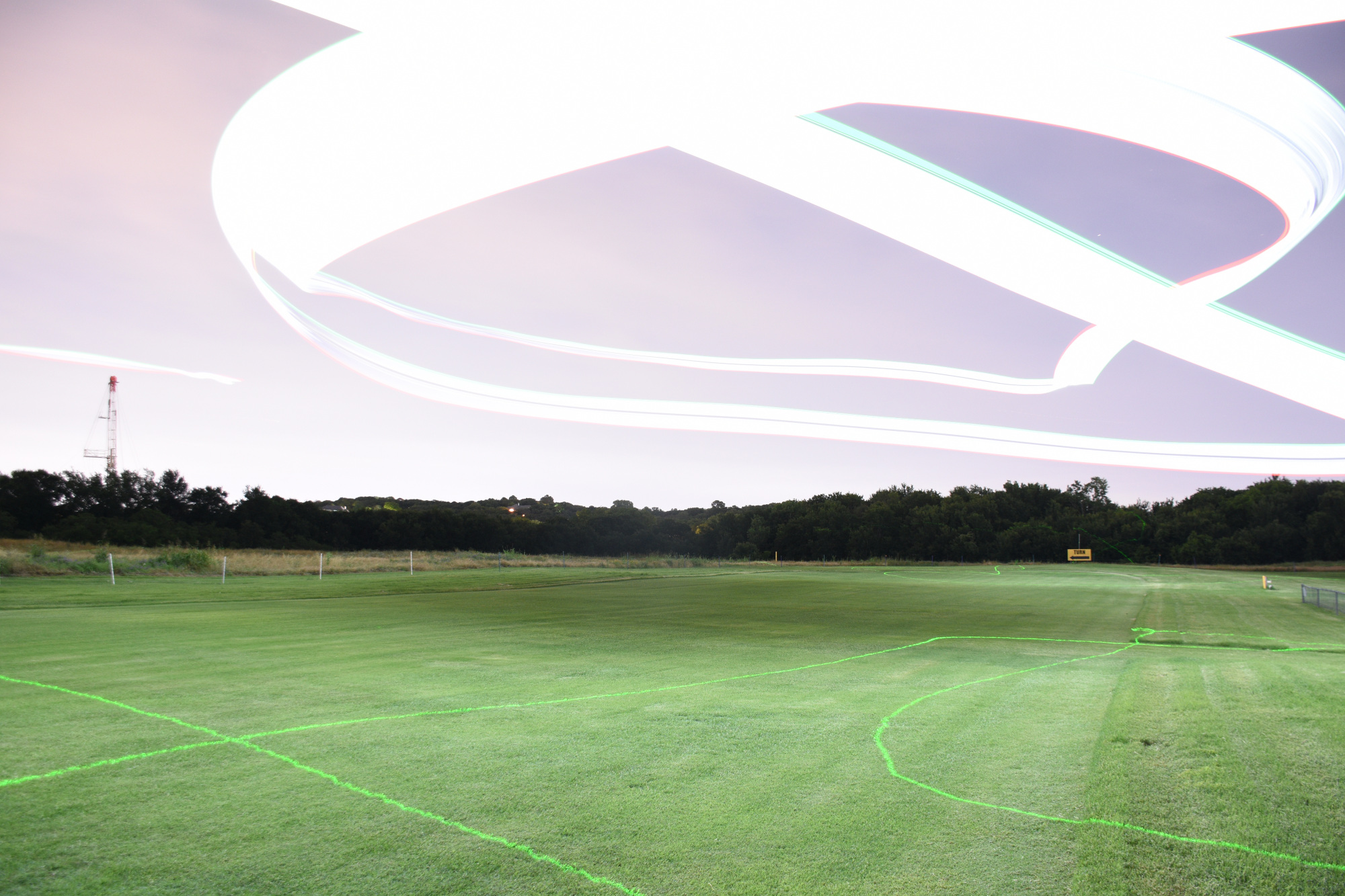
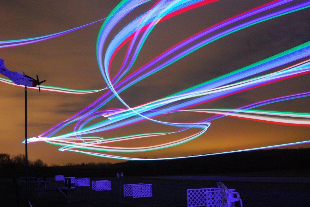
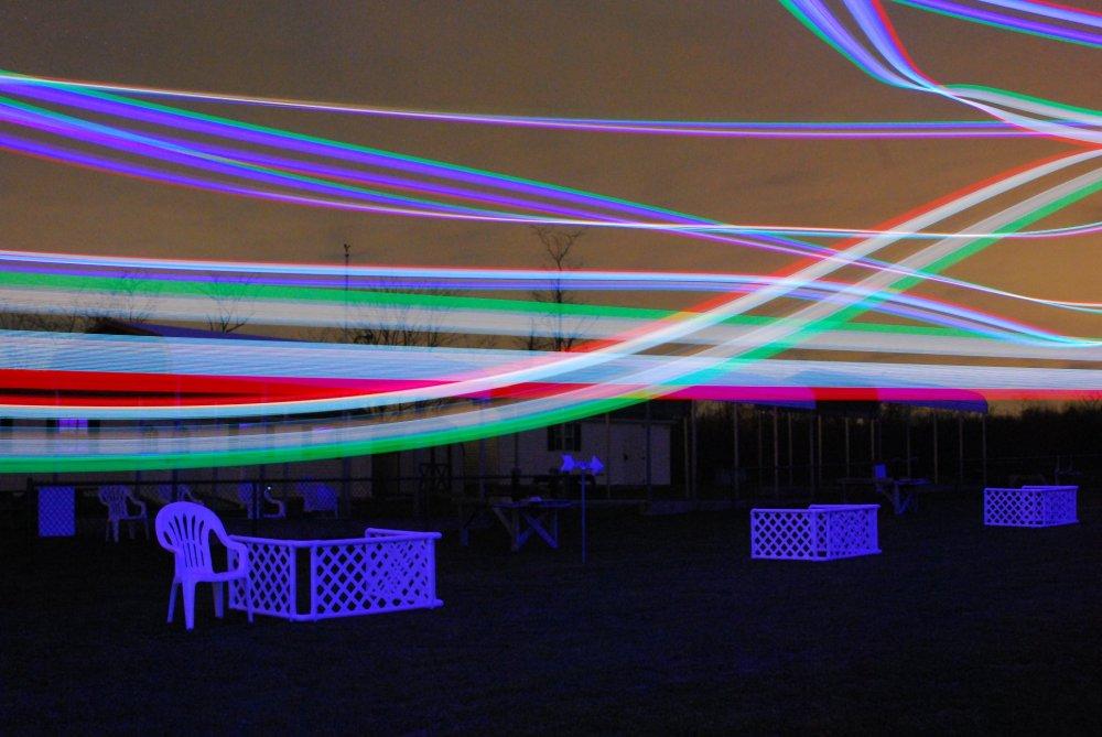
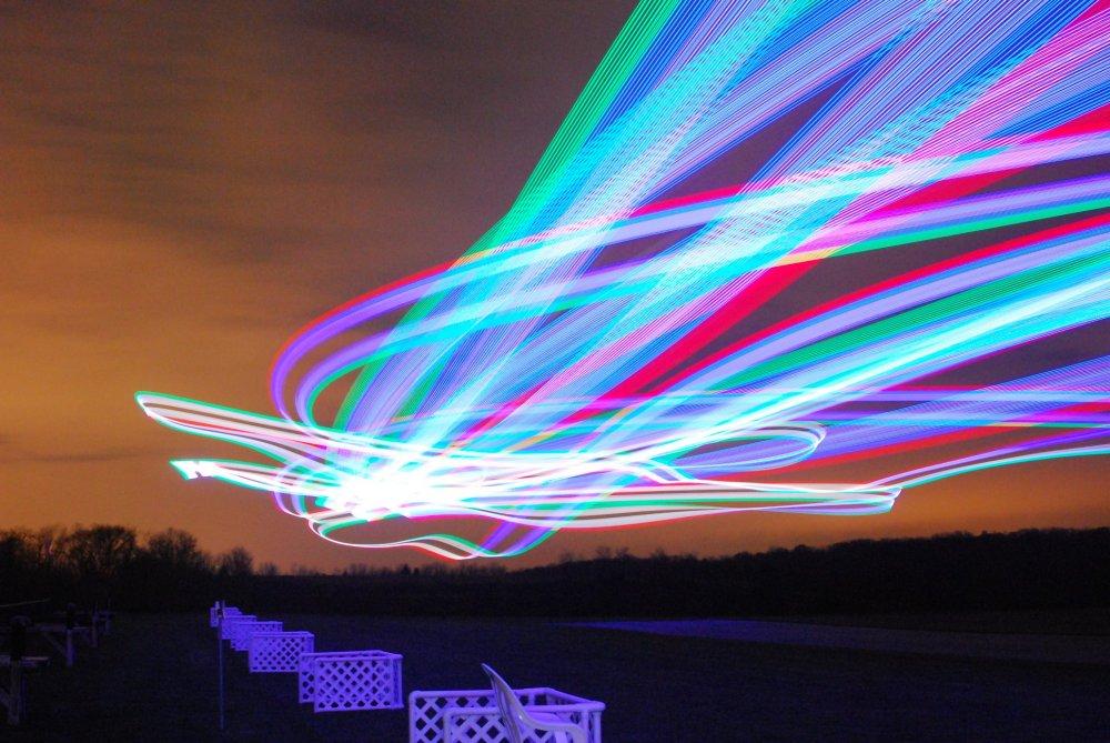
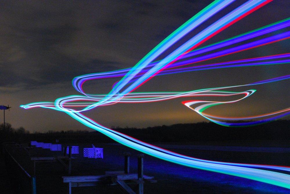
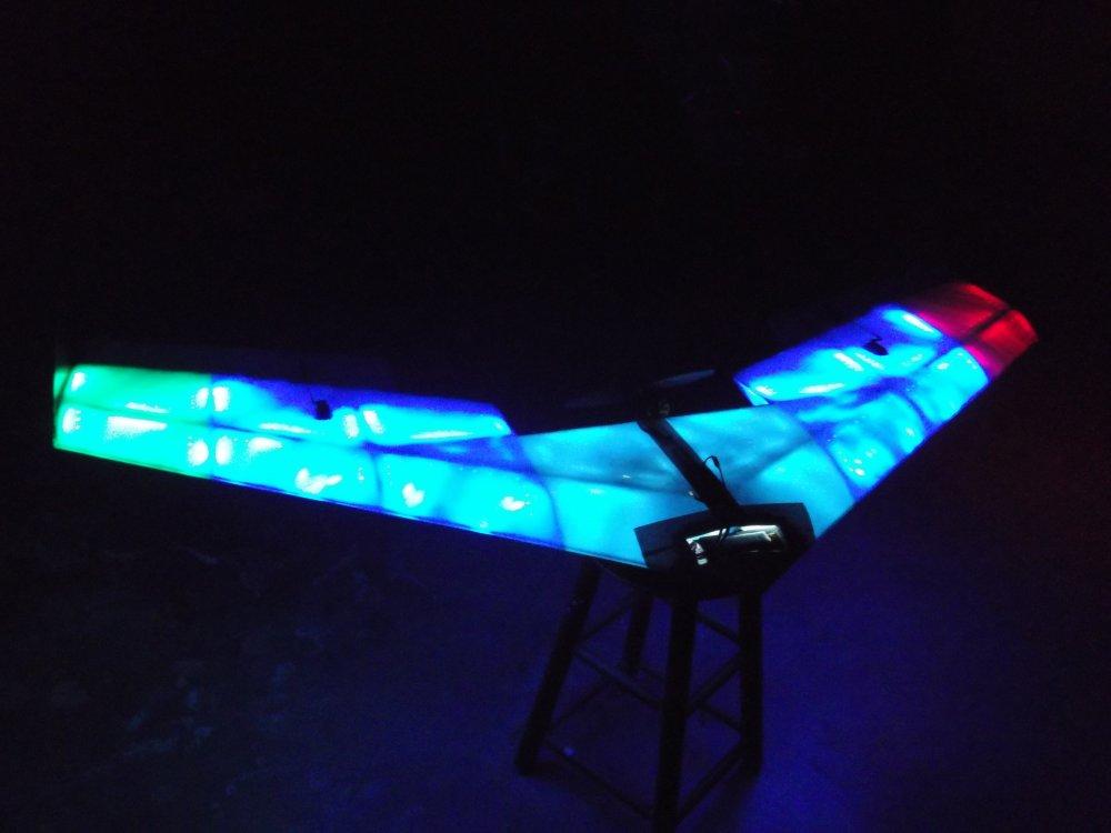
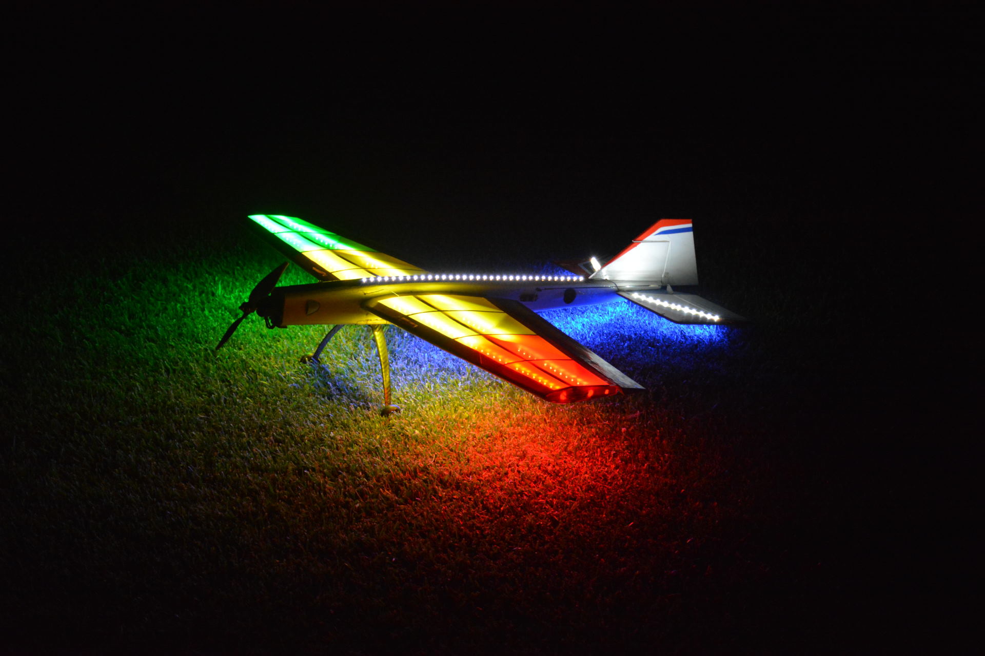
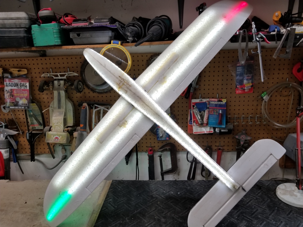
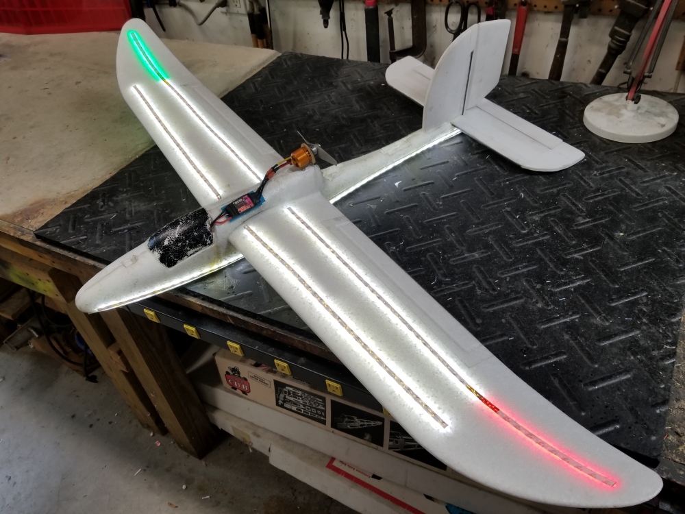
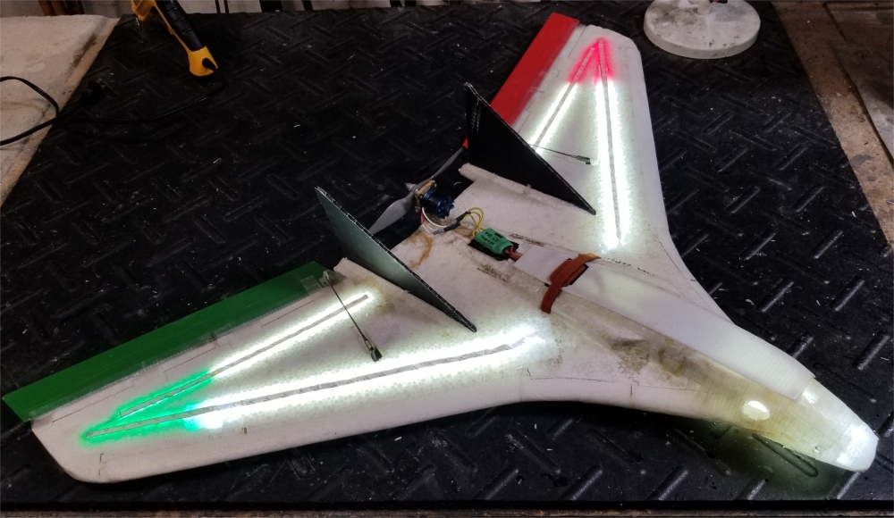
Night Wing & Camera Wing LED - Both of these 5 foot wings are covered with several hundred LEDs. All power comes from the main 3S 2200 mah lipo battery pack. The camera wing also has a mount in the nose to carry a HD movie camera but there is no downlink for this video. The photos below are time exposures of the Night Wing flying at my RC field, taken with my Nikon D80.

Phoenix LED - The fuselage and wings are filled with hundreds of blue, white, yellow, red, and green LEDs that are switched via an on/off button on the side of the fuselage. All power comes from the main 3S 2200 mah lipo battery pack.
 |
I built one of my Foame IIx 3D airplanes with the specific idea that it would be used for travel, and for night flying. I visited northern Sweden in February 2011 on business. I have been flying my old Foame IIx 3D plane for several years and thought it would make a good plane to take on trips if I could build a foldable version. I had finished it the night before I left, with modifications from the normal Foame IIx 3D airplane so I could fold it up, pack it, and re-assemble it with just clear tape. It has white, red, and green LED strips from HobbyKing. It worked very well and I flew it every day in northern Sweden for two weeks with no problems. The temperature ranged from -25C to 0C when I flew it. At the colder temperatures the servos slowed down after a few minutes in the cold. On our third night in Sweden, four of us got off work and drove about 90 km to get to the Arctic Circle. We all got our pictures at the Arctic Circle sign, and I wanted to say I had flown RC at the Arctic Circle. Here is the video of that cold (-21C) night flying experience. All power comes from the main 3S 800 mah lipo battery pack.