For What Its Worth
Remote Control Simulator: FMS - Flying Model Simulator http://simulator.home.pages.de
RC Helicopter Simulator: RC Sim Sikorksyhttp://home.zonnet.nl/blacksphere2/rcsim.html
I discovered this free piece of software by accident while surfing on eBay. Someone was selling cables to connect RC transmitters to some freeware RC simulator called FMS. BTW, don't bother buying the cable - it is very easy to make. I went to the FMS homepage, downloaded the current version of the simulator and found it to be an excellent piece of software. You can use the keyboard, joystick or your own rc transmitter to control the models in the simulator. RC Sim Sikorsky, more freeware, uses the exact same interface to read values from your rc transmitter.
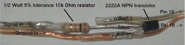
I have found several another set of pages on the web that detail how to use the program and interface your rc transmitter to your computer. These pages "FMS - the wonderful FREE RC Model Flight Simulator" are at http://home.introweb.nl/~erics/fms/ . From here you can get to the "FMS Interface" at http://www.heliguy.com/nexus/fmsinterface.html which has some excellent plans for the very simple interface cable required by FMS to use your standard rc transmitter. Here is my version of that same wiring. It is the exact same circuit as described on the page listed above - I have just rearranged the connections so that is not sticking out of the back of the parallel port connector. Whenever I plugged mine in, it got banged and I thought the wires coming from the transistor would break off eventually. Now they run together and are more easily protected.
The wires coming from the left in the picture below come from the rc transmitter. The wires going to the right go to your computer parallel port. The Tx signal passes through the resistor and transistor, and continues on to pin 10 of the computer parallel port. Ground passes through to pin 18 of the parallel port, while it is also connected to the emitter leg of the transistor. That's it - those are the only two required connections to the computer.
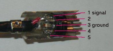
Where do "Signal In" and "Ground In" come from? Below are some pictures of the back of the Futaba 5 pin trainer connector. This used to be refered to as the "AM trainer cord connector", while the "FM trainer cord connector" was (and is) a 6 pin connection. Futaba has since gone to only the 6 pin trainer cord interface for all radios. It may be a sign how long I have been flying (and have failed to buy anything new in too long) that none of my radios have the 6 pin connection. I do have three Futaba radios (including an old Futaba FM!) that all use the 5 pin connector. I have not been able to find the pinouts for the 5 pin connector, so I had to do a little experimenting. I pulled my trainer cord apart. Everything is a straight pass-thru from one side to the other with the exception of pins 1 and 2. Those two pins crossover in the trainer cord. Because a trainer cord can be plugged-in either way (master/student), it must accept data on one line while passing data on the other. Pin 1 is the signal from the transmitter. In a trainer cord, that signal on pin 1 is crossed over to pin 2 at the other end of the cable, where the other radio reads it on pin 2.
The bottom line is that pin 1 is where you read the signal from the
transmitter. Pin 3 is ground. Note that you are looking at the back of the
connector here with the second half of the metal guard removed. DO NOT short pins 4
and 5.
|
|
If you do not have a trainer connector on your transmitter, you should
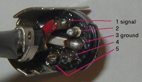
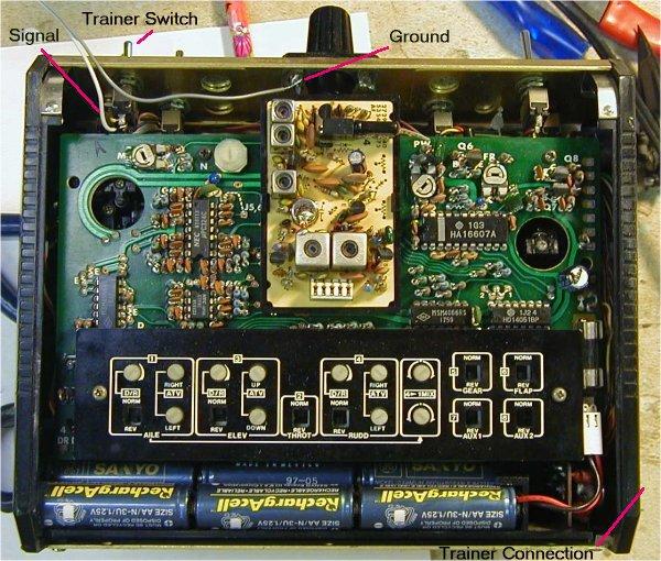
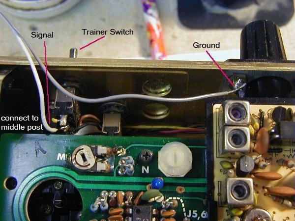
still be able to get the Tx signal. Below are some shots of the inside of the same
radio (Futaba 7ch AM Gold) that I used while experimenting with the above connector.
This radio has a trainer connector, but the connections also exist inside. I had
soldered my signal and ground wires directly to the connections inside the transmitter
before I had the pinouts figured out for the 5 pin connector. The two pictures below are
thumbnails, so click on them to see exactly where you need to solder on the inside of the
transmitter. The trainer switch on the top of the transmitter controls which signal
goes to the RF section of the transmitter. It is spring loaded so that the
internally generated signal (usual configuration) is transmitted. When the trainer
switch is held by the instructor, the signal coming from the student box is transmitted by
the instructor's radio. The center post of the trainer switch is the common
contact. Whatever comes through the center post goes to the RF section. That
is what you want to read for the signal. Any good ground spot is ok for
ground. If you have a good voltmeter, the signal should be about 4.7 volts on a
Futaba radio. I haven't experimented with my other radios yet.
 |
 |
How to make a blind nut / lock washer combination:
The solution requires a little solder, flux, blind nut, lock washer, and bolt to fit
those last two. Run the bolt through the blind nut as it would normally go (with the
'spikes' facing the bolt head). Then run it through the lock washer up to the point where
it comes in contact with the plastic. You want a good screw connection, but you do not
want the bolt to be touching the plastic (that is important - you will need all the metal
you can get to carry the heat away from the plastic insert). When the bolt is fed through
the blind nut and the lock washer, back it off until the lock washer is just touching the
blind nut. Now swab a generous helping of flux on the metal nut and washer. Next, apply
the solder and try to get it to flow nicely around the connection between the nut and
washer. If you keep the heat on too long, you will melt the plastic insert, so try to get
it done in a hurry. When you have a good connection, remove the bolt to make sure you
haven't soldered it in place (I never have done that, but I have melted the plastic, so
that's the main worry). I have yet to lose a bolt in this configuration. This setup is on
a Phaeton II top wing hold-down and engine mounts in several planes.
Pressure coefficient calculations of any airfoil:
Go to my Software Page for a complete listing
of programs and code libraries I have online. Among those programs is a complete source
listing and executable to compute pressure coefficients of any one airfoil, or group of
airfoils. Also available are airfoil coordinate files and links to other locations with
airfoils available for download.
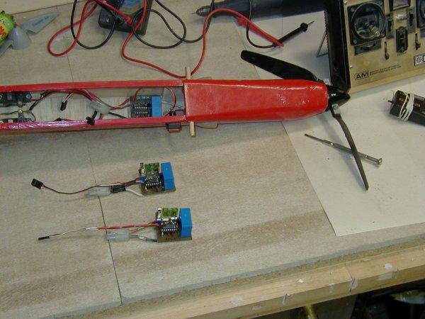
On-Off relay controller for electric models:
Stefan's Electric R/C
Web Site has a big set of pages with plans for electric on-off relays and speed
controls. I have built three of these on-off relays and they work great. I
made two small modifications to the plans as
they are on his web site. I could not get the relay to trigger at the correct
throttle setting (about 1/2). R5 is specified as 15k ohms, but if you build this
relay and can not get it to trigger correctly, change R5 to about 10k ohms. It will
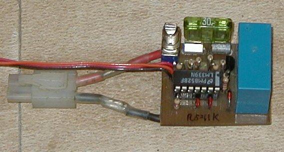
trigger with a shorter pulse width. The other modification I made was to physically
move the relay over so that components will fit on the board better. The modified
printed circuit board (PCB) is shown below. All circuits are identical to the
original; this just makes the transistor and diode easier to fit on the board. Full
details on the construction can be had at Stefan's
Electric R/C Web Site.
|
|
 |
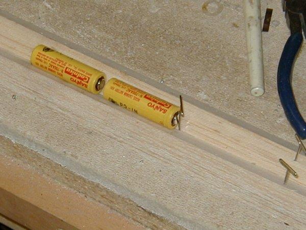
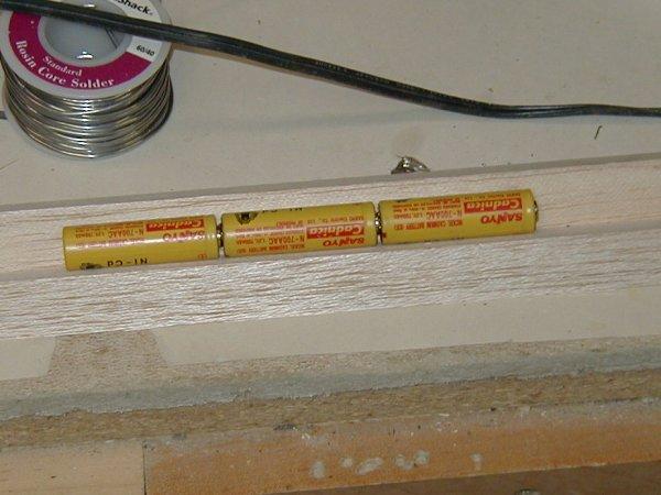
Soldering NiCD batteries together in series:
Creating your own NiCD battery packs from single nicads is much cheaper
than buying preassembled packs. However, it is sometimes difficult to get the cells
to match up correctly for a row. I use two balsa or spruce triangles pinned next to
each other on a building board. Put the batteries in the channel that the triangles
make and put a pin in the middle of the channel. The pin will keep the battery from
sliding when you solder the batterties together. Put the + side of one battery and
the - side of the other battery facing each other and put solder on the iron tip.
There should be enough solder to reach both batteries. Using a 30-40 watt iron, keep
the heat on the batteries for approximately 15-20 seconds. Pull the iron out and push the
batteries together. The pin holding one battery will allow you to do this with one
hand. Do not keep the heat on too long as that will damage the batteries. If
you do not heat the solder up enough, you will not get a good solder connection. When the
batteries are bonded well you should not be able to pull them apart easily. Last thing to
do is to check to make sure there is no short-circuit. You can put any number of
cells in a row with this method.
|
|
Reversing any type servo
Note: Please don't attempt this unless you are very good with a soldering iron, and have a basic understanding of electronics. One wrong connection and you will zap your servo. Fixing the electronics of servos is more expensive than buying a new one, so you might want to try this out on an old servo the first time you do it.
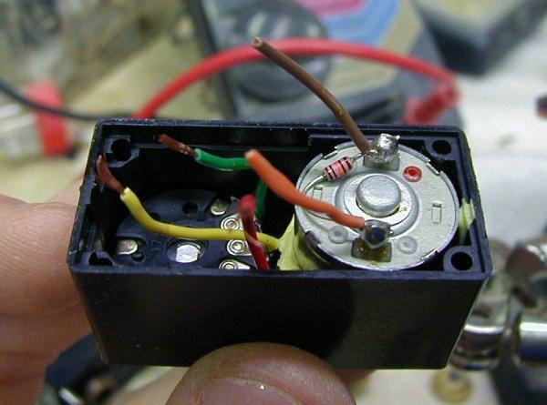
Most of the time, radios can handle servo reversing, but sometimes you may have to reverse a servo's rotation. If you have a special circumstance, such as dual servos running off of the same signal but facing different directions, you may need to reverse the direction of rotation of a servo. If you need to reverse a servo, you need to make four wiring changes inside the servo. DO NOT reverse the + and - power supplies to the servo. The electronics inside the servo that control rotation expect power to arrive + on the red wire and - on the black wire. If you change those, you will fry the electronics. Take a look at the picture below. This is a Hitec HS-300 standard servo, but most servos have similar insides.
You don't need to know how a servo works to change servo rotation direction, but it
helps. If you don't care, skip down. All servos have a motor which turns
the gearing, and a potentiometer (also called a pot, or variable resistor) which feeds
back to the electronics the current position of the servo control shaft. As the pot
moves, the resistance that it returns to the brains of the servo cause the brains to
increase and decrease the voltage going to the motor. The brains try to keep the pot
resistance equal to a derived value from the signal the servo receives from the RC
receiver on the signal wire (usually white). Note: The RC receiver sends this signal
as a set of pulse-width modulated "pulses", not a resistance value (ohms).
That is why I say it is a derived value.
|
Step #1: The potentiometer has three wires coming off of it. You
must swap the two outside wires from the potentiometer to the circuit board. Leave
the middle wire alone. On the Hitec HS-300 (see picture), these wires are red and
green. Leave the yellow (center) wire alone. Step #2: The motor has two drive wires, and sometimes a third black ground wire coming off the metal casing. You must swap the two drive wires from the circuit board to the motor. On the Hitec HS-300, these wires are orange and brown. Leave the black (ground) wire alone. |
That is it. Recheck your connections - if everything looks good, go for it. Some servos have direct circuit board to pot or drive motor connections. These are harder to reverse, but can still be done. You must make cuts to the printed circuit board (pcb) and put in new wiring to replace the cut traces. It is difficult, and this wire may not fit into the casing. But it can be done.
Modifying Hitec servos:
Before you attempt something like this yourself, you need to verify that the pots in the swapped servos have equal values. If you don't know what that means, you probably shouldn't be trying something like this. Good luck on your servo modifications. If you have any questions, please feel free to email me.
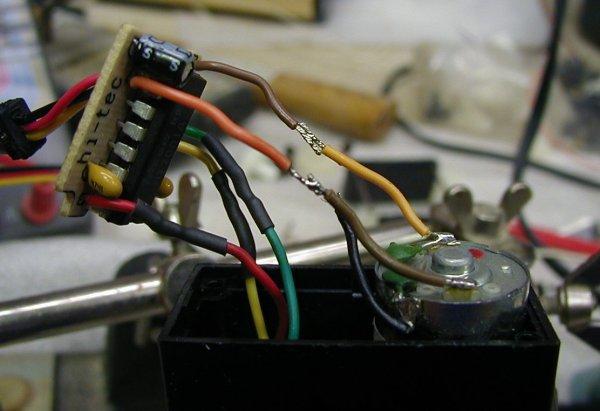
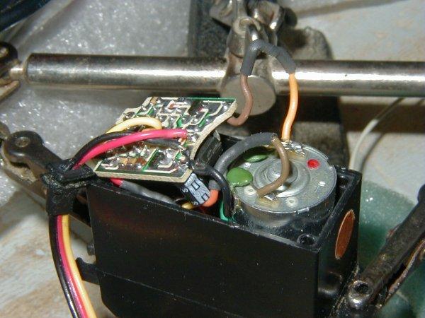
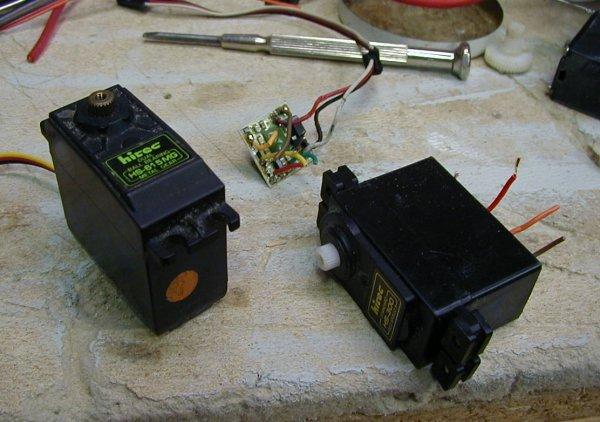
I bought a big bunch of servos on eBay. Two were Hitec servos; an HS-300 standard and an HS-651MG dual ball-bearing, metal gear servo. The 300 worked fine. The 651 electronics were fried (I got it very cheaply). Wouldn't it be nice to get a working ball-bearing servo out of the deal? Simple - I swapped the electronics in the two servos. These two servos use 5k potentiometers, so they were easy to hook up. The pcb from the HS-300 fits fine inside the HS-651MG. I cut all the wires from the pots and drive motor to the pcb in the 300, resoldered them into the 651, and used shrink-wrap to protect the wires. You can see the new connections in the pictures below and the HS-300 pcb being pushed into the casing of the HS-651MG in the middle picture. The final result can be seen in the third picture: one good HS-651MG dual-bearing, metal gear servo; one HS-300 standard servo with no electronics, and the fried electronics from the HS-651MG.
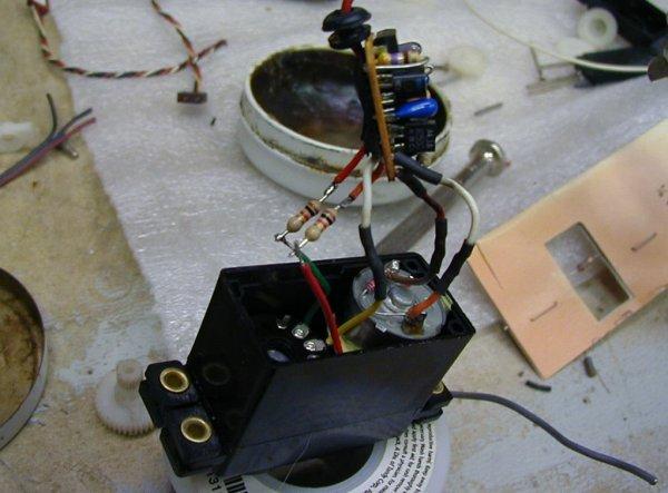
So now I have this HS-300 with good mechanics and no electronics - what should I do
now? Well, I bought another set of servos on eBay and one had bad mechanics, but
good electronics. So I swapped those electronics out and put them into the
HS-300. The pot in the servo with bad mechanics was a 3.3k pot. I added a
1k resistor in series with the pot to get the return values up close to the expected 5k
Ohm. You can see those resistors soldered in place in the last picture.
You will probably ask why I didn't leave the HS-300 alone and swap the electronics out of
the third servo directly into HS-651MG. I bought them in the wrong order and
modified them as they arrived.
|
|
|
|
Determining center of gravity:
 |
Determining the center of gravity for new airplanes is usually pretty straight forward. Just make sure the plane balances on the thickest point of the wing and you will probably get a decent first flight. But do you have a weird design? Canard ... forward swept wing ... flying wing ... any combination of these ? Ron Van Putte published an excellent article on determining the center of gravity for most planes in the June 1980 issue of Model Aviation. It is available here: http://www.palosrc.com/instructors_corner.htm I have taken the equations in this article and put them in to two Excel spreadsheets. Try either one - they have the wing layouts a little different. Just enter the airplane's numbers in the highlited yellow areas and the results are displayed. CG.xls CG2.xls |