6' Relay Pink Wing FPV + 4' Razor Wing FPV : Radio and Flight Controller Setup

 
6' Relay Ping Wing FPV + 4' Razor Wing FPV + RadioMaster TX16S Transmitter with Crossfire Module

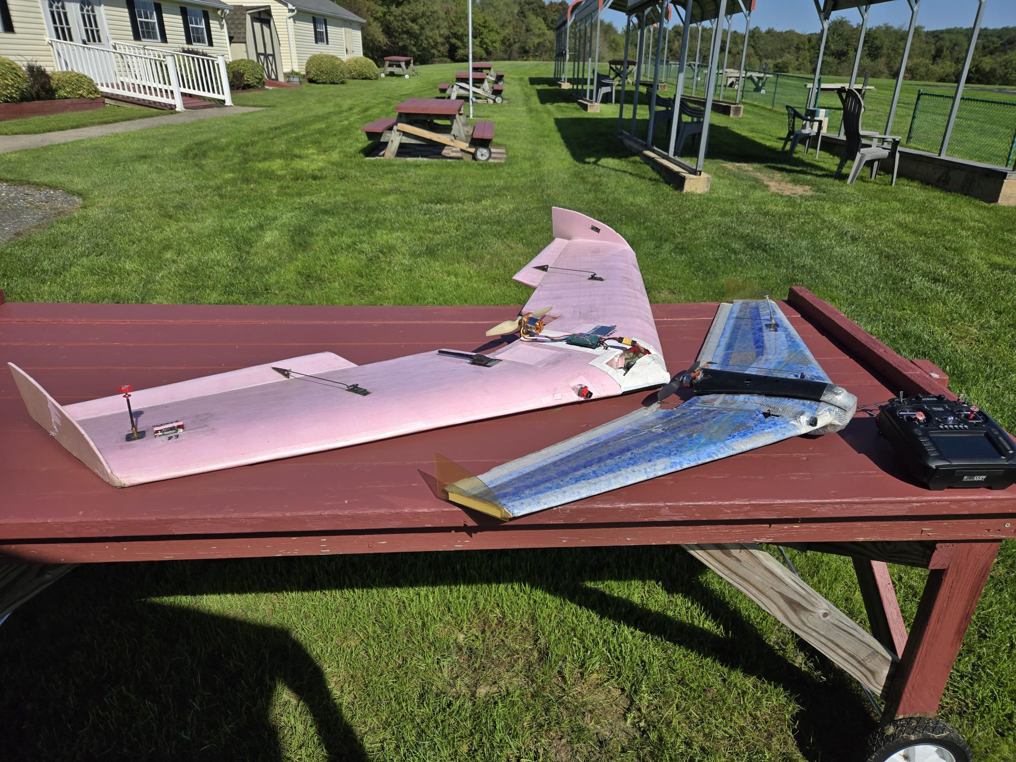
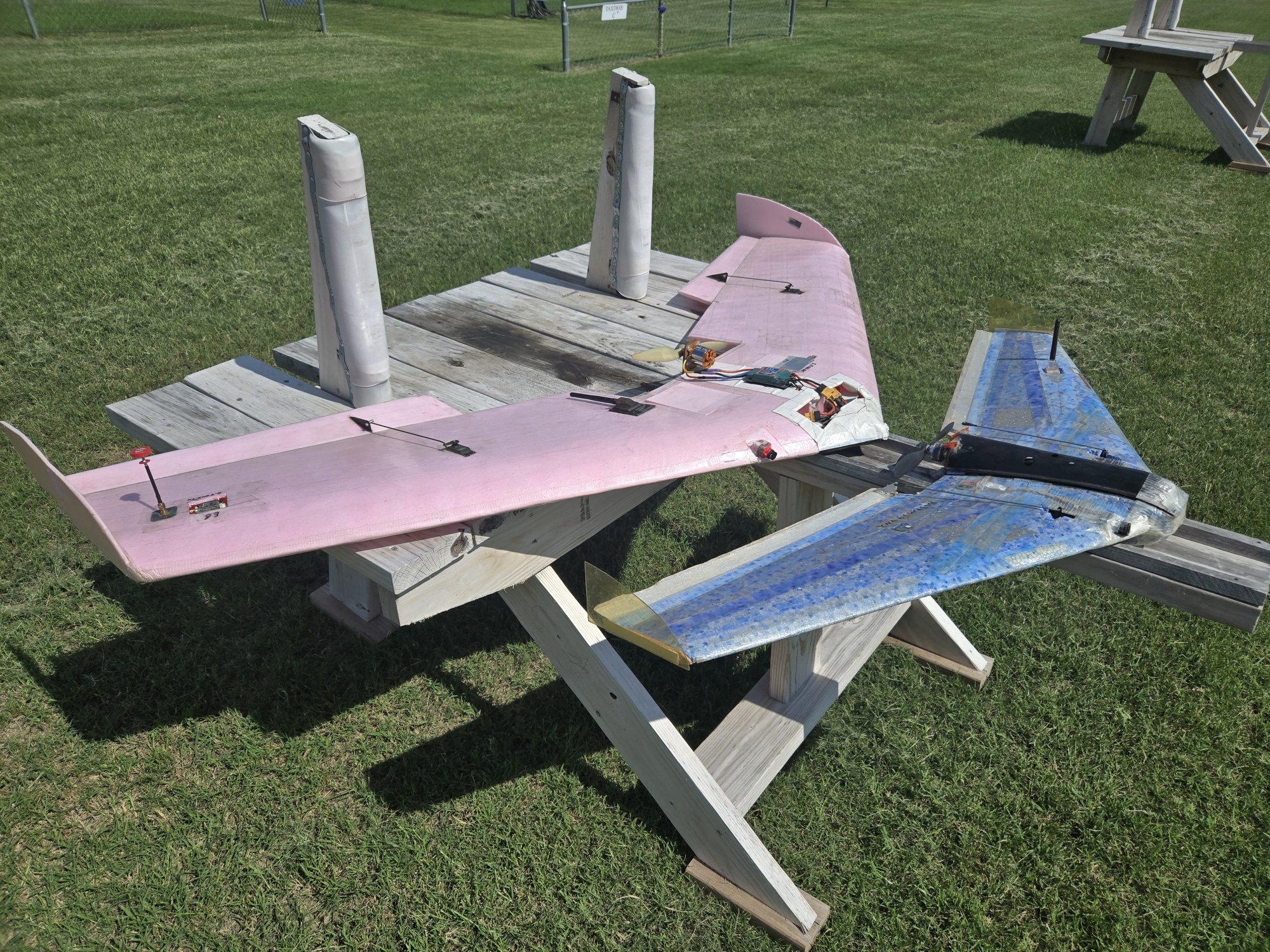
This 6' wingspan pink foam FPV wing is used as an airborne relay for controlling the Razor 4' FPV wing. This flying combination uses the most complicated radio and electronics setup that I have ever implemented for the RC hobby.  The EdgeTx and iNav software settings are defined below.  The photos above shows the Relay and Razor wings together; the image on the left shows them after their first dual flight in Maryland in 2024, and the image on the right shows them after their first dual flight in Texas in 2026.  Power for the 6' wing comes from a 480 outrunner with a 50A ESC, running on a 3S lipo.  FLYING - FPV

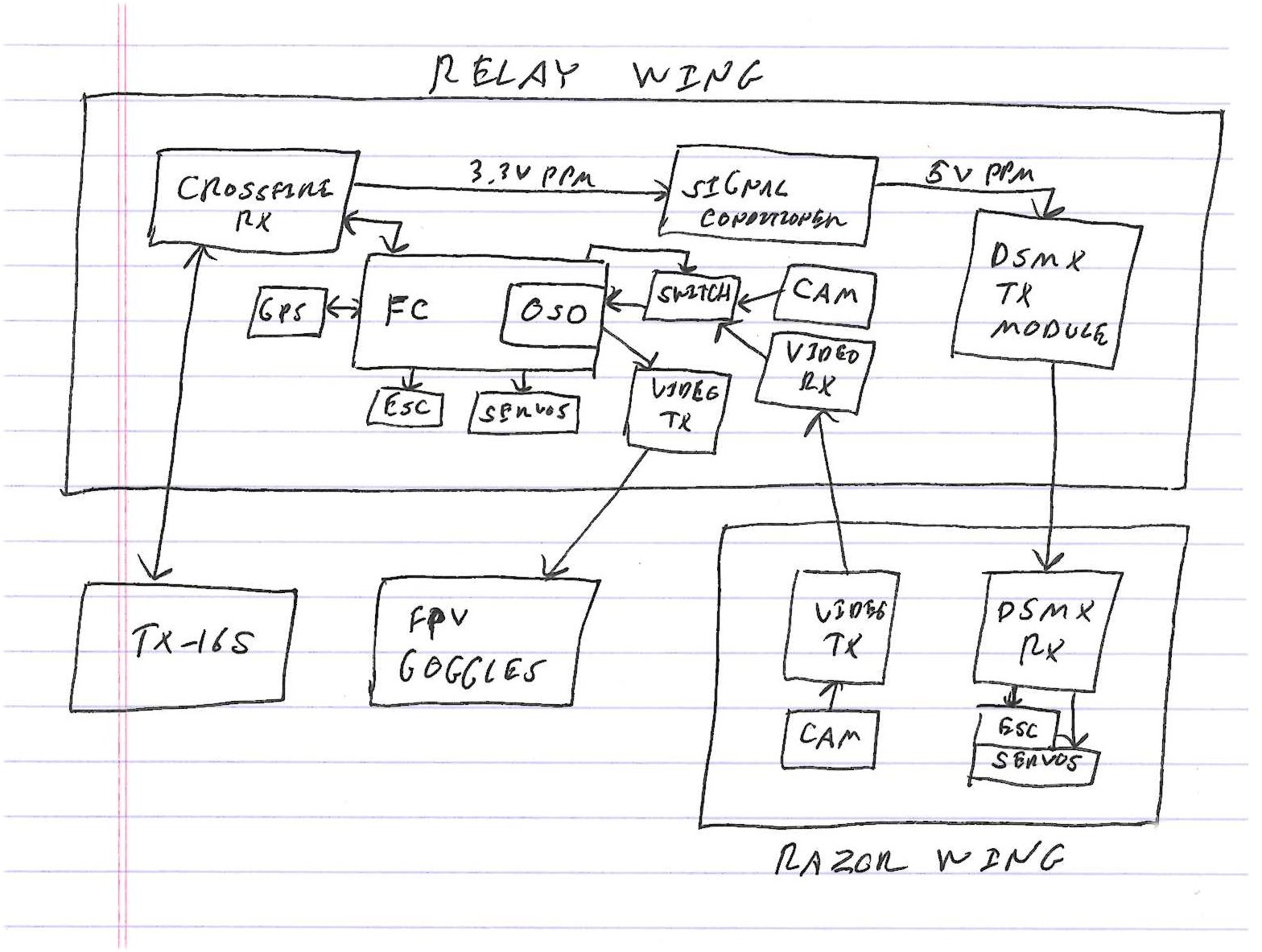
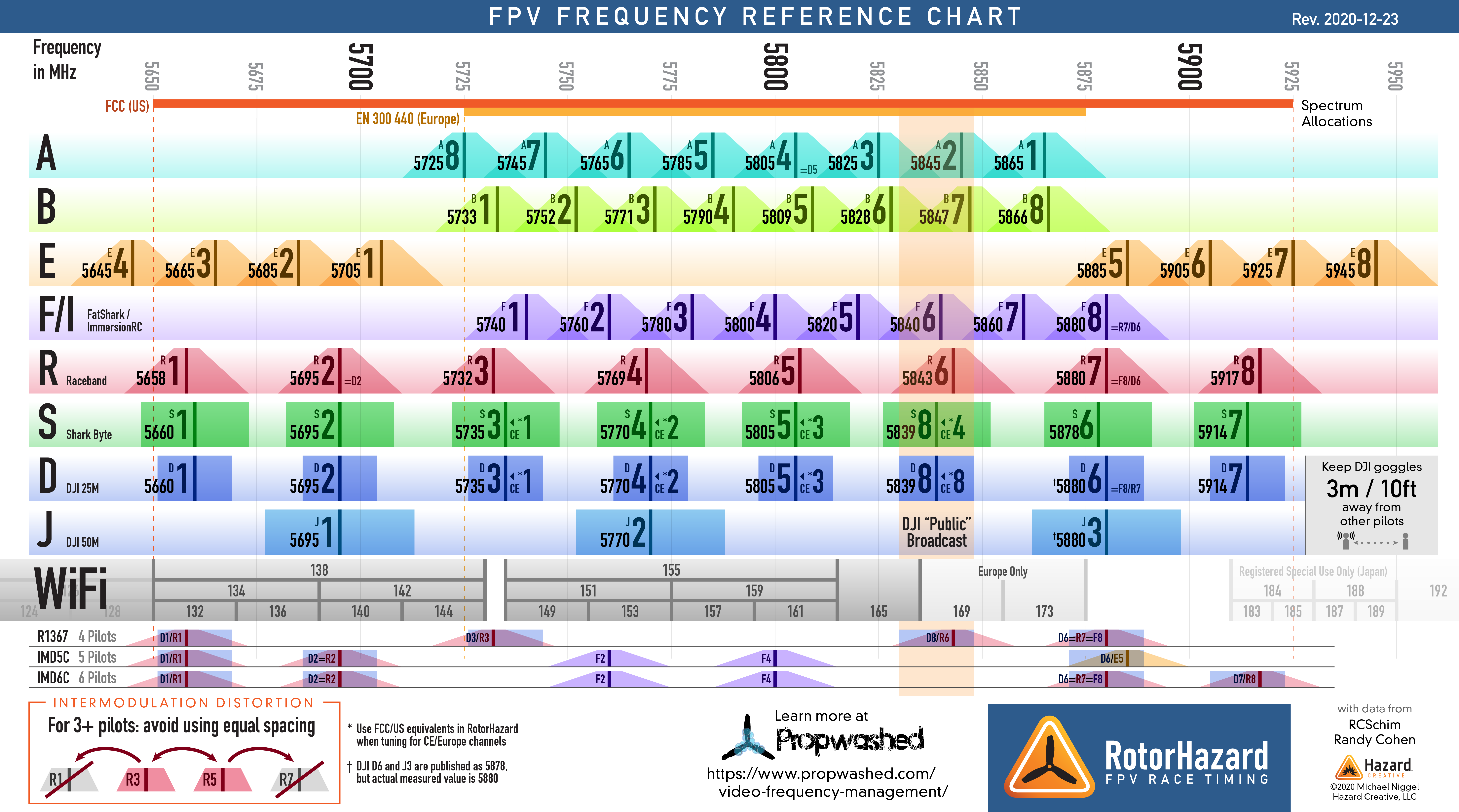
Both planes are controlled from a single RadioMaster TX16S transmitter running EdgeTx software, with a Crossfire RF module. The TX16S transmitter does not directly control the Razor wing, as the control link goes from the TX16S to the Relay wing via Crossfire, and then from the Relay wing Crossfire receiver to a Lemon DSMP transmitter module in the Relay wing via PPM, and then back down to the Razor via DSMX. The video link is similar but in the opposite direction; the Razor’s video transmitter is on 5.8 GHz frequency B, which is received by a video receiver in the Relay wing. The Relay wing then re-transmits that video signal using its own video transmitter on 5.8 GHz frequency A. Video goggles on the ground monitor frequency A.  I keep frequencies A and B as far apart as possible, such as E3 and E6.

Using this wing as a relay station for both control uplink and video downlink allows for line of sight (LOS) from the ground to the FPV Relay wing flying high to the Razor FPV wing flying low. The Relay wing has a GPS receiver and a F4 flight controller running iNav 7 software, allowing for autonomous navigation. The Relay wing is launched first, flown to altitude, and then placed in position and altitude hold; a circling loiter. The Razor wing is then launched and flown normally, with its control and video links passing through the Relay wing. Once the Razor wing has landed, the Relay wing is taken out of autonomous loiter and landed normally. The Relay wing also has its own on-board camera. A remote controlled video switch in the Relay wing is used to select which signal is sent to its video transmitter; the Relay wing’s own camera or the video signal received from the Razor wing. A SmartAudio connection from the Relay wing flight controller to its video transmitter allows for instant video transmitter power control from the ground via iNav's logic functions.

Fatshark Goggles Recording of FPV Downlink,
GSWAM, Ft Worth, Texas, 3 August 2026


GoPro Hero 10 4K (+ Gryoflow 0.5) + Fatshark Goggles,
GSWAM, Ft Worth, Texas, 14 August 2026


Flying Two RC Aircraft at Once, Relay Wing + Razor Wing,
GoPro Hero 10 4K + GoPro Session 5 4K + Fatshark Goggles,
GSWAM, Ft Worth, Texas, 16 August 2026


GoPro Hero 10 4K (+ Gyroflow 0.5 + Telemetry) + Fatshark Goggles,
GSWAM, Ft Worth, Texas, 3 September 2026


Fly Three RC Aircraft at Once, Relay Wing + Razor Wing + DJI Mavik,
GoPro Hero 10 4K + GoPro Session 5 4K + DJI 4K + Fatshark Goggles,
GSWAM, Ft Worth, Texas, 3 September 2026


GoPro Hero 10 4K (+ Gyroflow 0.5 + Telemetry) + Fatshark Goggles,
GSWAM, Ft Worth, Texas, 4 September 2026


Fly Three RC Aircraft at Once, Relay Wing + Razor Wing + DJI Mavik,
GoPro Hero 10 4K + GoPro Session 5 4K + DJI 4K + Fatshark Goggles,
GSWAM, Ft Worth, Texas, 4 September 2026


Omnibus F4 V3 flight controller, with baro pressure sensor, 3-6S input (PDF manual by Von Flori)
- flashed and configured iNav 7.1.1 and iNav OSD via USB
- flight controller has 5V regulator, also provides power to GPS & Crossfire Rx
- LC filter + large capacitor on main power at FC to condition and smooth voltage
- COM1 : SmartAudio control of video transmitter, switch on TX16S instantly sets low or high power
- COM3 : GPS
- COM6 : Crossfire uplink commands, downlink telemetry

Crossfire Nano Receiver (915 MHz) - to F4 flight controller COM6
- SmartAudio from flight control (Crossfire Rx SmartAudio is not used)
- Rx channel 1 : PPM out - to Lemon DSMP Transmitter Module via signal conditioner
- Rx channel 3 & 4 : Crossfire Rx/Tx - to F4 Flight Controller running iNav 7.1.1

Eachine TX1200 5.8 GHz Video Transmitter
- on video frequency A : this video signal is transmitted to FPV goggles on the ground monitoring channel A
- video frequencies A and B need to be separated as much as possible (E3 and E6 when possible)
- SmartAudio to F4 flight controller COM1, allows changes to frequency and power through iNav

Boscam/Skyzone RC305 5.8 GHz Video Receiver
- on video frequency B : this video signal is received from the Razor FPV aircraft
- video frequencies A and B need to be separated as much as possible (E3 and E6 when possible)
- frequency selection via DIP switches within band E for this model video receiver
- RealAcc TFP-Mini Triple Feed Patch Antenna facing down inside wing

Lemon DSMP Transmitter Module (2.4 GHz)
- Crossfire receiver PPM output goes to Lemon DSMP Transmitter Module PPM input through home-made signal conditioner
- Home-made signal conditioner
  - Crossfire receiver output 3.3V (LVTTL) PPM signal is raised to 5V (TTL) PPM signal using two transistors and 5V reference (7805)
  - Lemon DSMP Transmitter Module is also powered by the 7805 voltage regulator on the signal conditioner
  - DSMP module power supply valid range = 4.8V to 12V
- Lemon Stabilized Receiver in Razor FPV aircraft is bound to Lemon DSMP Transmitter Module
- Lemon DSMP Transmitter Module can be removed from Relay Wing and plugged directly into TX16S to fly Razor FPV without Relay Wing

Beitian BE-220 GPS receiver - to F4 flight controller COM3

Mista MS-519 FPV Nose Camera

ViFly Two Input Video Switch
- Onboard nose camera output and video Rx output are fed to video switch as input channels 1/2
  - Input 1: Onboard Nose Camera
  - Input 2: Boscam 5.8 GHz Video Receiver :  This video signal is received from Razor FPV aircraft transmitting on frequency B
- Video switch output selection is controlled by PWM signal from F4 flight controller PWM 6 : video switch output goes to FC OSD input
  - FC OSD overlays Relay Wing data (GPS, aircraft name, battery voltage, timer) to top of video feed
  - Razor OSD overlays Razor Wing data (aircraft name, voltage, timer) to bottom of video feed
  - FC OSD output goes to 5.8 GHz video transmitter


Remote Power Switch
- Controls power to relay equipment : 5.8GHz video receiver and Lemon DSMP Transmitter Module
- Power switch selection is controlled by PWM signal from F4 flight controller output PWM 5
- This equipment can remain off if second aircraft is not being flown
- There is a physical switch on the relay equipment, but a method of remote power control is also needed
to allow the 5.8 GHz video receiver and DSMP transmitter modules to be remotely turned off after the Razor FPV wing is landed but while the Relay wing is still airborne.
- This allows for the Razor to be landed and left powered on, with the controls signals being sent to the Relay wing not passed on to the Razor via the DSMP transmitter module.  i.e.  After manually landing the Razor, I do not want the commands sent to the Relay wing to cause the Razor motor to come on.


Relay + Razor Checklist Sequence

  • Goggles : Power ON
  • Goggles : Record ON
  • TX16S : Power ON
  • Relay Wing : Power ON
  • Razor : Power ON
  • Relay Wing + Razor preflight:
    • Relay Wing : Confirm control and elevon direction (6 buttons – Manual)
    • Relay Wing : Confirm GPS
    • Relay Wing : Confirm video from on-board camera (Switch SB – onboard camera)
    • Razor : Confirm control (Switch SE - relay equipment ON, Razor bound to DSMP module)
    • Video : Confirm video relay from Razor to Relay Wing to Goggles (Switch SA – set video Tx HIGH and LOW)
    • Relay Wing : Confirm video from receiver (Switch SB - remote camera)
    • Relay Wing : Confirm video from on-board camera (Switch SB – local camera)
  • Relay Wing : GoPro Hero 4K : Record ON
  • Relay Wing : Launch (Switch SF – motor ARM)
  • Relay Wing : Confirm control (6 buttons – Rate, Horizon)
  • Relay Wing : Loiter (6 buttons – Position Hold)
  • Relay Wing : Confirm Loiter Hold and Altitude Hold
  • Relay Wing : Video switch to video receiver (Switch SB – remote camera)
  • Razor : Set Stability Gain (Switch SH Stability ON/OFF + Dial S2 Stability Gain)
  • Razor : Confirm control and elevon direction
  • Razor : GoPro Session 5 : Record ON
  • Razor : Launch
  • Razor : Fly, adjust Stability Gain (Dial S2)
  • Razor : Land
  • Relay Wing : Set video switch to on-board camera (Switch SB)
  • Relay Wing : Turn off relay equipment – DSMP Tx + video receiver (Switch SE)
  • Relay Wing : Take out of loiter (6 buttons – Manual / Rate)
  • Relay Wing : Land wing (Switch SF – motor DISARM)
  • Relay Wing : Power OFF
  • Relay Wing : GoPro Hero 4K : Record OFF
  • Razor : Power OFF
  • Razor : GoPro Session 5 : Record OFF
  • TX16S : Power OFF
  • Goggles : Record OFF
  • Goggles : Power OFF


Radio Setup:

Crossfire Uplink Channels from RadioMaster TX16S :
1 - 8 : Throttle, Rudder, Elevator, Aileron, Aux1, Aux2, Aux3, Aux4

Eight channels of control allows for :
Relay Wing : Throttle, Roll, Pitch, Motor Arm [on/off], Flight Mode [ manual, rate, horizon, position + altitude hold, return home, autotune ], relay equipment power [ on/off ], video switch selection [ on board camera/video receiver from Razor ], video transmitter power via SmartAudio [ high/low ]
Razor Wing : Throttle, Roll, Pitch, Rate Stabilizer [ on/off ], Stabilizer Master Gain [ continuous low - high ]

iNav Channel Input Order : TREA1234
iNav uses  :  Throttle,
Rudder, Elevator, Aileron, aux1, aux2, aux3, aux4
 - Rudder channel is not used by iNav for Relay Wing,
Aileron polarity as expected by iNav [ left = 1000
μs / right = 2000 μs ]

Razor uses : Throttle,
Rudder, Elevator, Aileron, aux1, aux2, aux3, aux4
 - Aileron channel is not used by Razor,
Rudder polarity as expected by Razor Lemon Stabilized Receiver [ left = 2000
μs / right = 1000 μs ]
 - Rudder command is copy of Aileron command with inverted polarity


Relay Wing Architecture

Relay Wing Controls

Throttle            (1) Relay Wing & Razor Throttle

Rudder            (2) Razor Roll (= inverted Relay Wing Roll command)

Elevator           (3) Relay Wing & Razor Pitch

Aileron             (4) Relay Wing Roll

SH                   (5) Razor Stabilizaion ON/OFF

SE                   (5) Relay Wing Equipment ON/OFF (middle – no effect) : Power to DSMP module & Video Receiver

SF                   (6) Relay Wing Motor ARM/DISARM

6 Buttons         (6) Relay Wing Flight Modes

SB                   (7) Relay Wing video switch ON-BOARD CAMERA/VIDEO RECEIVER

SA                   (7) Relay Wing Video Tx RF Power – HIGH/LOW (middle – no effect)

Dial S2:           (8) Razor Stability Master Gain, low to high


Crossfire Uplink Channel 5 = Aux1 : Switch SH + Switch SE
- Razor stabilization on/off  + Relay Wing relay equipment ( video receiver + Lemon DSMP Module ) power on/off

- Switch SH ( 90% mix ) :
  - high : PWM = 1960 μs (1500 + 460) : Lemon Stabilized Receiver in second aircraft looks for PWM > 1500 μs for STABILIZER ON
  - low  : PWM = 1040 μs (1500 - 460) : Lemon Stabilized Receiver in second aircraft looks for PWM < 1500 μs for STABILIZER OFF

- Switch SE ( 10% mix ) :
  - high     : iNav logic condition looks for PWM = 1908 μs (1960 – 52) or PWM = 988 μs (1040 – 52) [ SE-high offset from SH-high or SH-low ]
     --> this causes flight controller servo output #3 to be high, which turns power switch ON
  - middle : no effect to current command
  - low      : iNav logic condition looks for PWM = 2012 μs (1960 + 52) or PWM = 1090 μs (1040 + 52) [ SE-low offset from SH-high or SH-low ]
     --> this causes flight controller servo output #3 to be low, which turns power switch OFF


Crossfire Uplink Channel 6 = Aux2 : Switch SF + 6 Buttons

- Relay Wing motor arm/disarm + Relay Wing flight mode


- Switch SF ( 50% mix ) :
  - high : PWM = 1756 μs (1500 + 256) : iNav logic condition looks for PWM > 1500 μs to ARM
  - low  : PWM = 1244 μs (1500 - 256) : iNav logic condition looks for PWM < 1500 μs to DISARM


- 6 Buttons ( 15% mix ) :

  - each iNav flight mode has two valid ranges : Button 1 - 6 offsets from SF-high or SF-low
  - Button 1 : iNav flight mode Pass-Through / Manual
  - Button 2 : iNav flight mode Rate
  - Button 3 : iNav flight mode Horizon
  - Button 4 : iNav flight mode Position Hold / Loiter + Altitude Hold
  - Button 5 : iNav flight mode Return Home
  - Button 6 : iNav flight mode Autotune

    - when button 4 or 5 is active, the Aileron command is centered so that roll commands meant for the Razor do not affect iNav Position Hold [ nav_user_control_mode = atti ]

  • this is done with logic conditions in EdgeTx where aileron is only overlaid to RC channel 2 when (not button 4 AND not button 5)

   - throttle commands meant for the Razor do not affect iNav Altitude Hold [ nav_fw_allow_manual_thr_increase = off ]
   - elevator commands meant for the Razor do not affect iNav Altitude Hold [ because it is in altitude hold ;-) ]


Crossfire Uplink Channel 7 = Aux3 :  Switch SB + Switch SA
- Relay Wing video transmitter power + Relay Wing video switch

- Switch SB ( 50% mix with modification for middle position ) :
  - high & middle: PWM = 1756 μs (1500 + 256) : iNav logic condition looks for PWM > 1500 μs
   --> this causes flight controller servo output #4 to be high which in turn causes the video switch to pass on-board camera signal to OSD
  - low : PWM = 1244 μs (1500 - 256) : iNav logic condition looks for PWM < 1500 μs
   --> this causes flight controller servo output #4 to be low which in turn causes the video switch to pass video receiver signal (from second aircraft) to OSD

- Switch SA (25% mix) :
  - high : iNav logic condition looks for PWM = 1628 μs (1756 - 128) or PWM = 1116 μs (1244 - 128) [ SA-high offset from SB-high or SB-low ]
   --> this causes flight controller to use SmartAudio to set video transmitter to high power
  - middle : no effect to current command
  - low : iNav logic condition looks for PWM = 1884 μs (1756 + 128) or PWM = 1372 μs (1244 + 128) [ SA-low offset from SB-high or SB-low ]
  --> this causes flight controller to use SmartAudio to set video transmitter to low power

Crossfire Uplink Channel 8 = Aux4 : Dial S2
- Razor Lemon Stabilized Receiver master gain
 -
Dial S2 : continuously variable from 1000
μs to 2000 μs, low to high gain


F4 Flight Controller iNav 7.1.1

PWM Channel Outputs (mmix and smix): [ Flight Controller Outputs ]
PWM 1 : Motor 1 : MMIX 0 : Motor control to ESC
PWM 2 : Motor 2 : MMIX 1 : Not used, iNav reserves this channel for a second ESC due to the way timers work on ARM processors
PWM 3 : Servo 1 : SMIX 1 + 2 : Elevon Left - receives 50% stabilized pitch + 50% stabilize roll
PWM 4 : Servo 2 : SMIX 3 + 4 : Elevon Right - receives 50% stabilized pitch + -50% stabilize roll
PWM 5 : Servo 3 : SMIX 5 : Logic conditions on uplink channel 5 drive this output to 1000
μs or 2000 μs for relay equipment remote power switch control : on/off
- two ranges are valid for switch ON : switch SH high + switch SC high / switch SH low + switch SC high
PWM 6 : Servo 4 : SMIX 6 : Logic conditions on uplink channel 7 drive this output to 1000
μs or 2000 μs for video switch control : video feed 1/2
- two ranges are valid for each video switch condition : ( switch SB = 1750
μs + switch SA any position ) > 1500 μs ,  ( switch SB = 1250 μs + switch SA any position ) < 1500 μs

<insert image capture of iNav Programming Tab


PPM Signal Conditioner, 3.3V LVTTL to 5V TTL