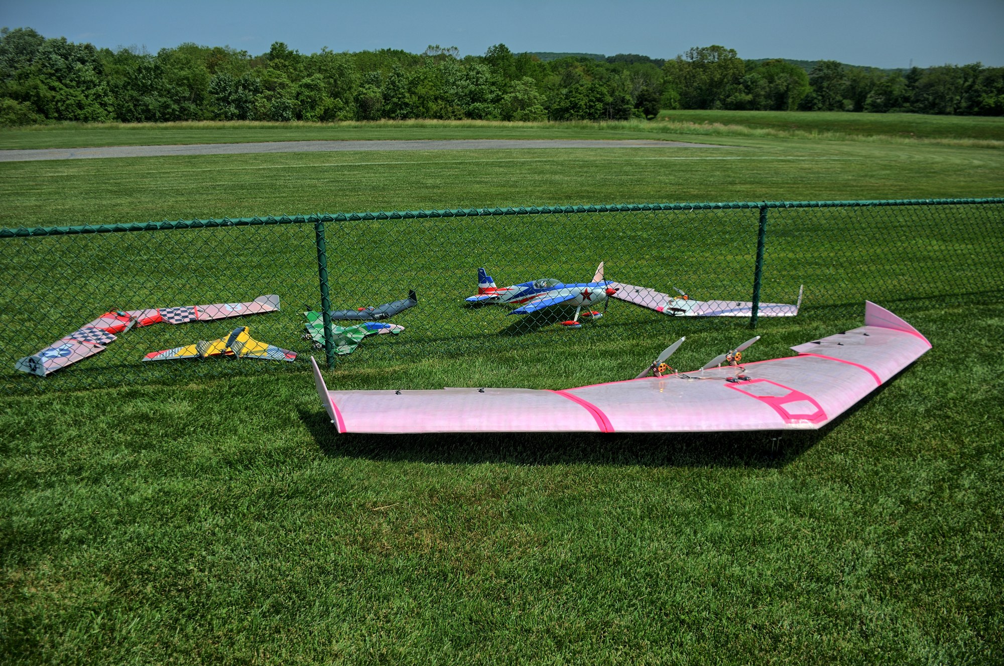
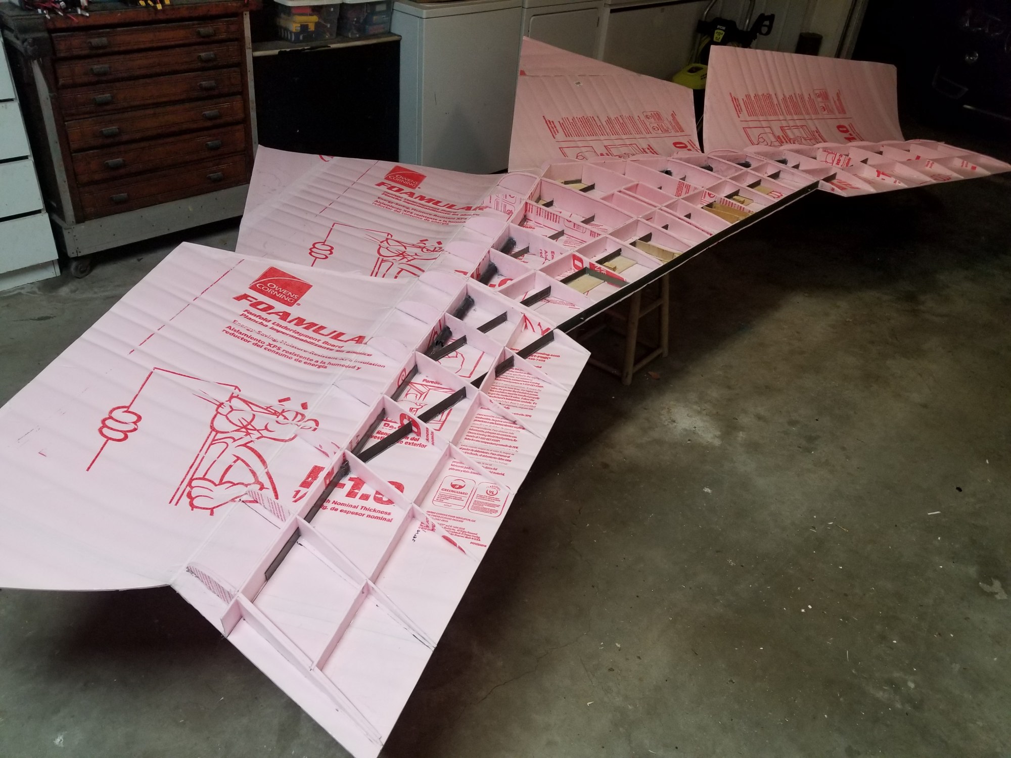
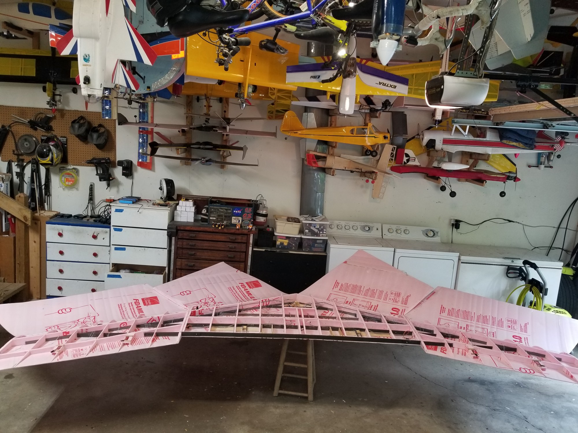
13' Pink Wing
I scaled up my 6' wingspan flying wing design to 13'. The center section is 5.5' and each plug-in wingtip is 3.75'. Strength comes from lots of carbon fiber spars running across the wing, and all structure and shape is 1/4" thick Owen-Corning's Pink fan fold foam. Here is an aerial video of two flights of this wing on 1 October 2023, shot with a Gear 360 camera.
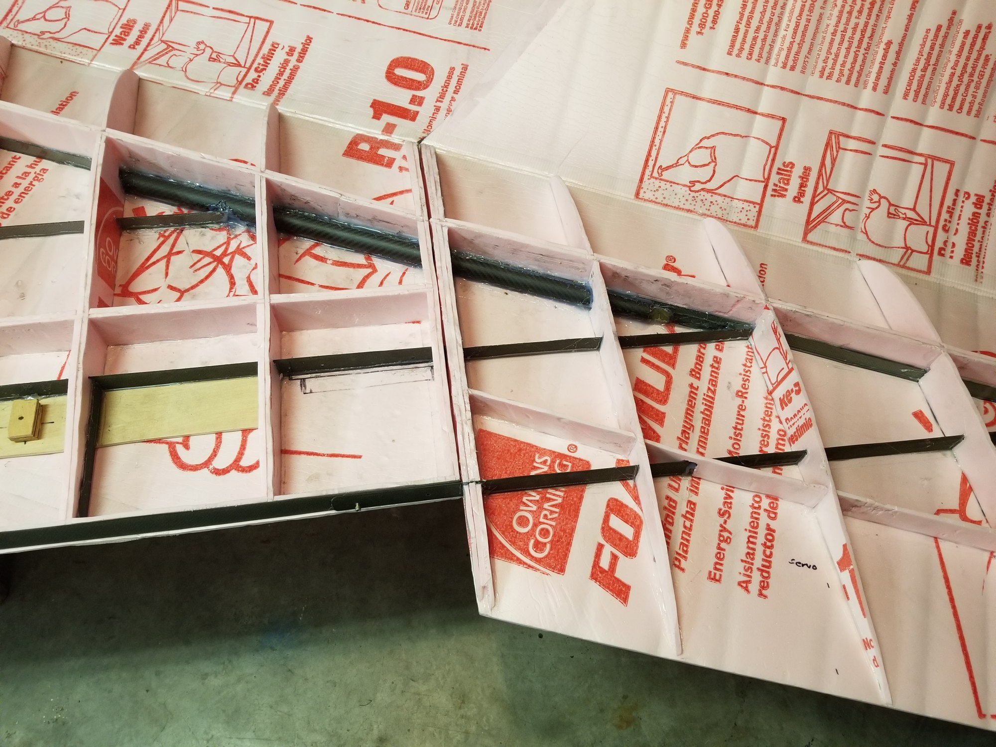
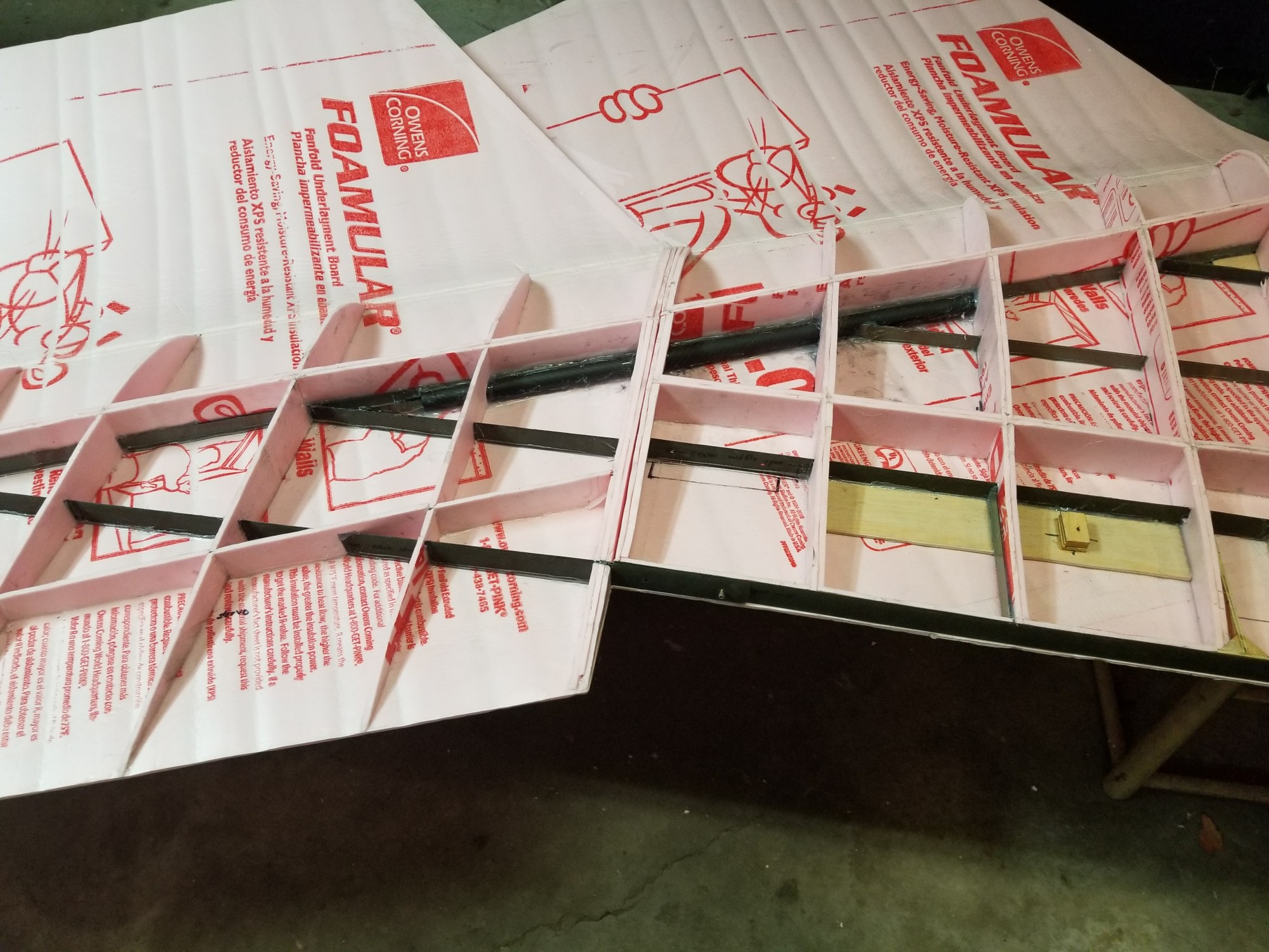
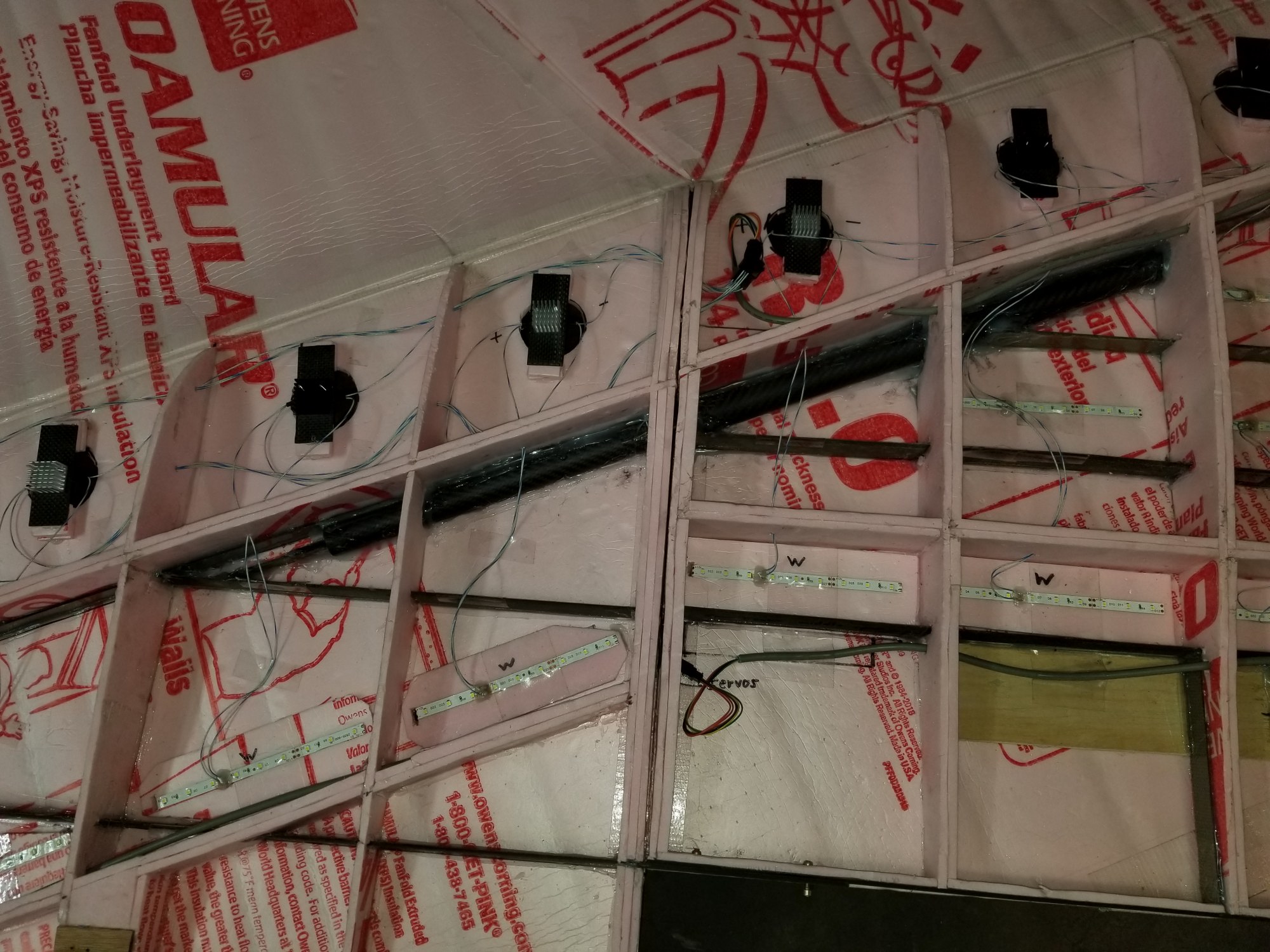
I bought carbon fiber tubes on Amazon as wing tubes. The center section of the wing has the female 25x23x420mm tubes, and the wingtips have the male 22x20x500mm tubes. The male tubes also have extra carbon fiber spars vertically aligned and glued in place.
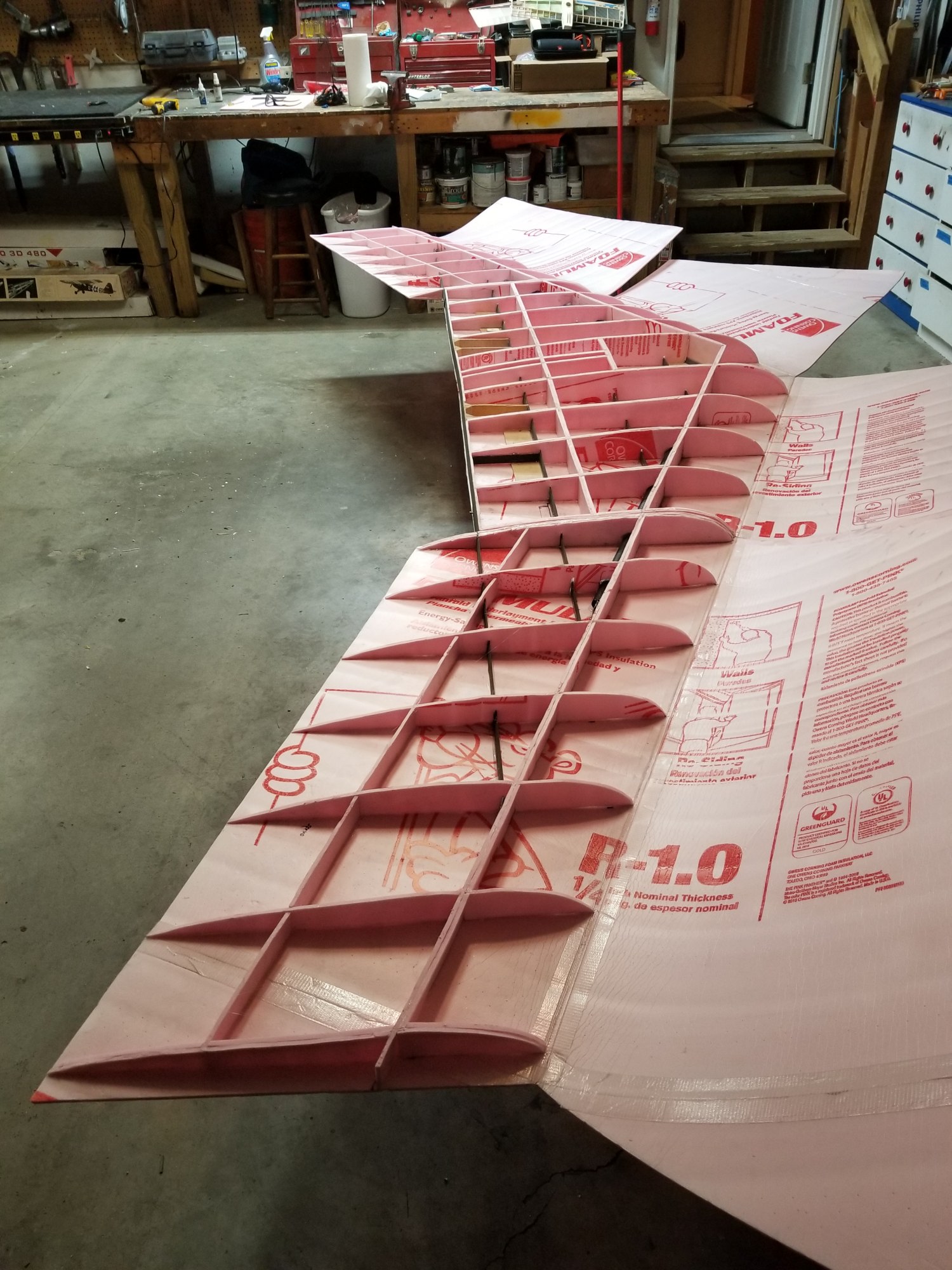
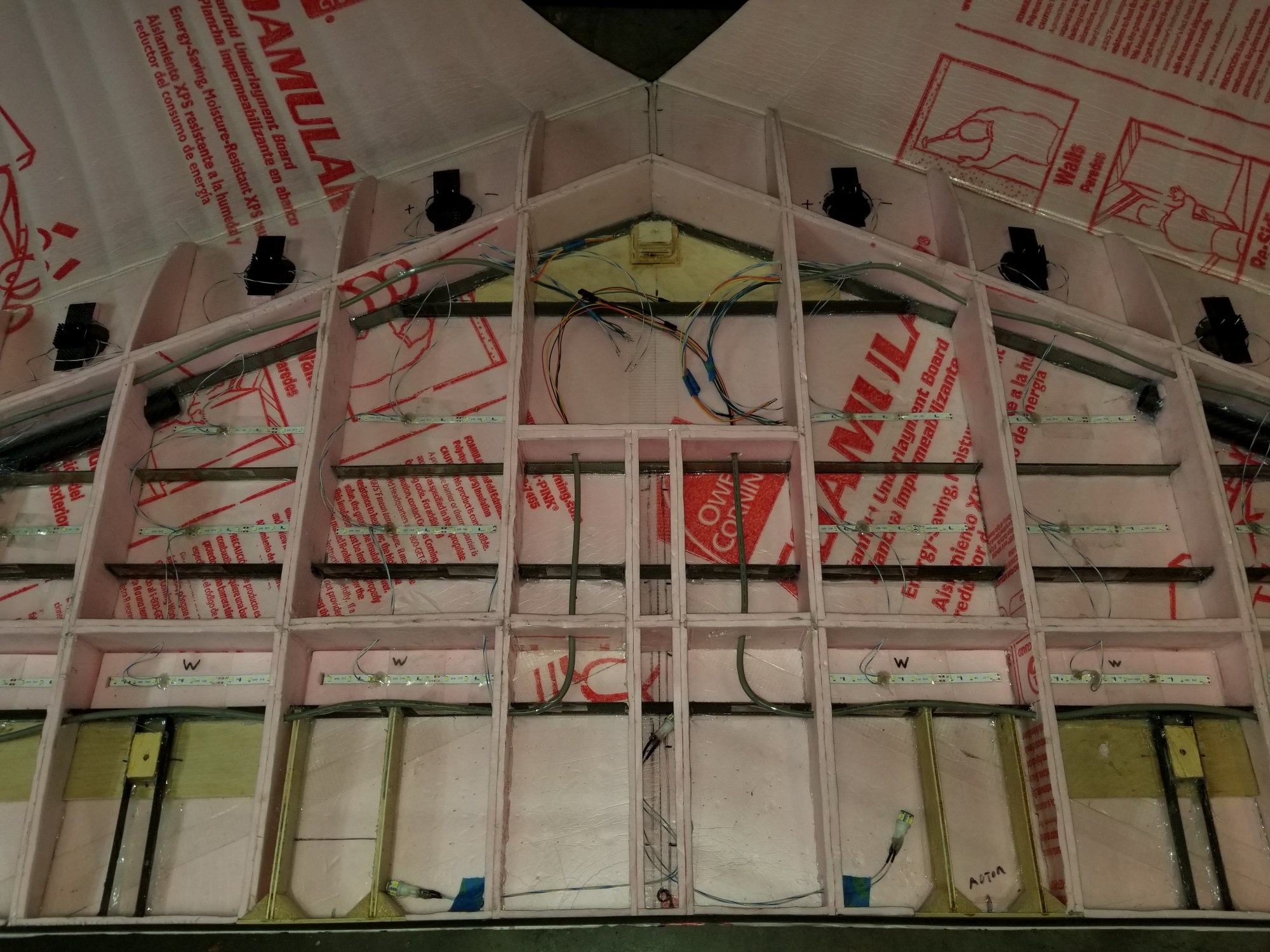
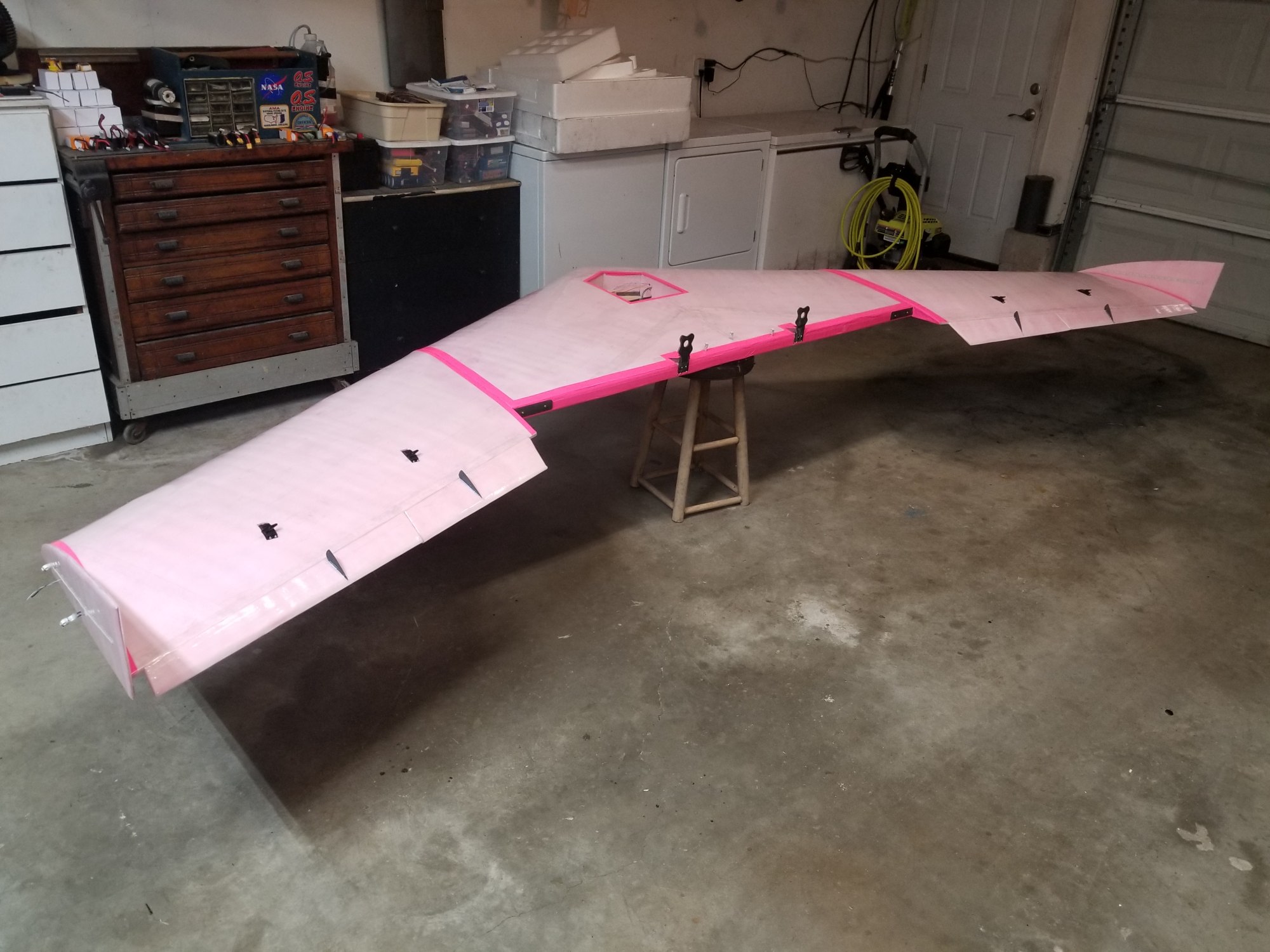
In this first set of photos, you can see the internal spar and rib layout, and the carbon fiber tubes joining the center and wing-tip sections.
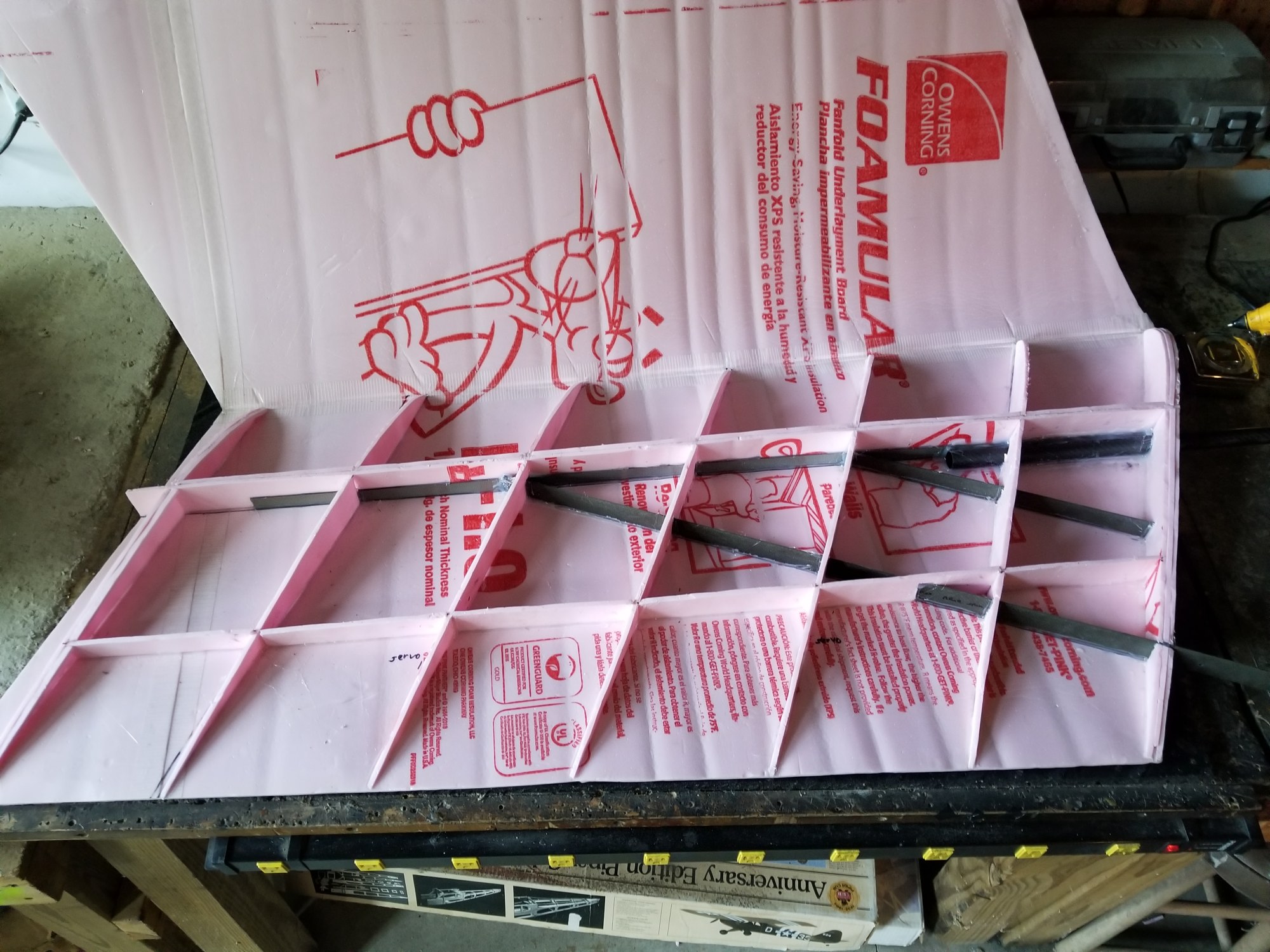
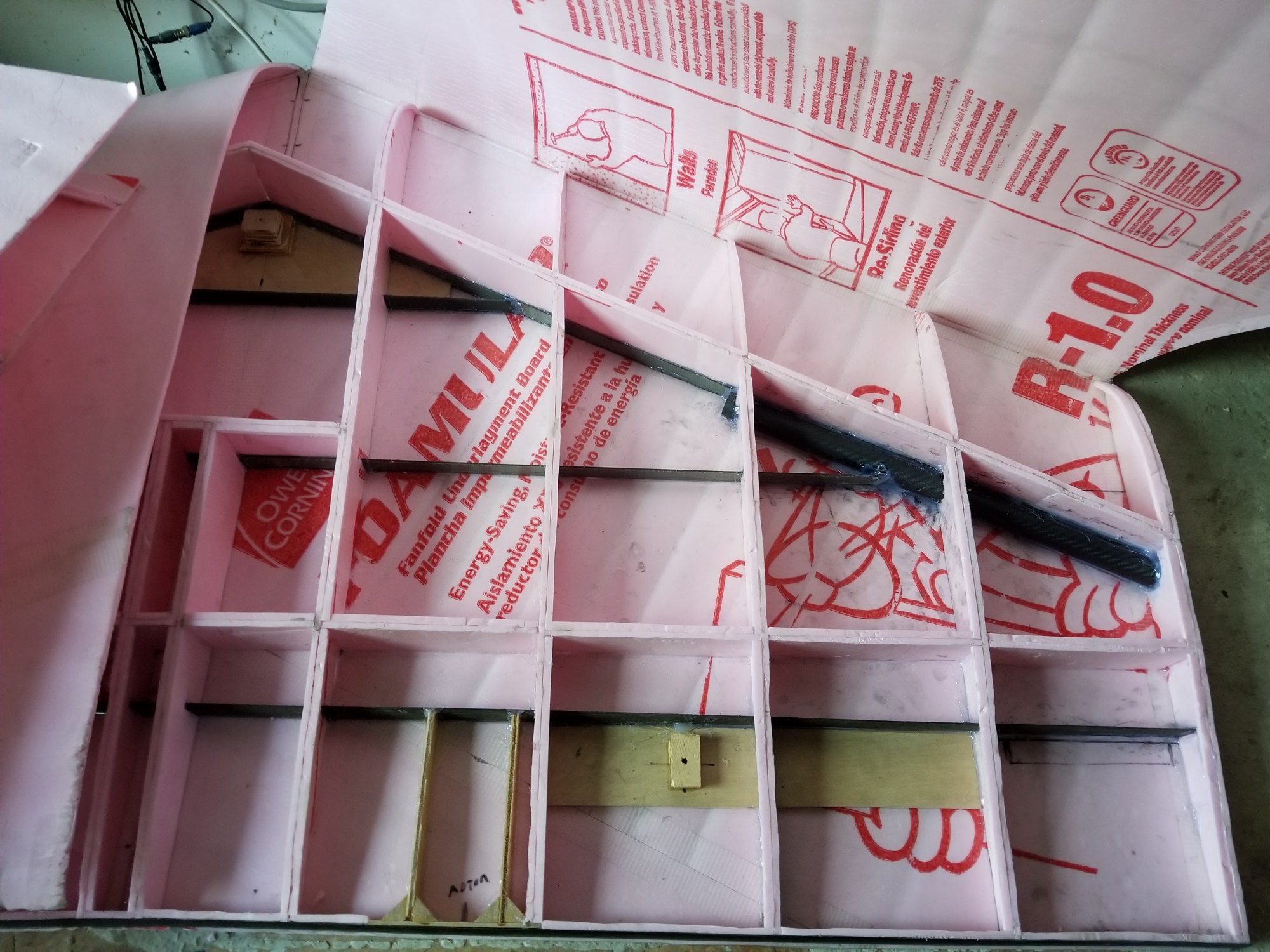
The main structure was complete at this point, but before folding over the top sheets of foam and gluing them in place, I needed to add all the servo mounts and electronics.
I added servo mounts and servo wiring, and decided that this plane should be full of LEDs. There are white LED strips facing downwards all across the span of the wing. There are red and green LED strips facing down at each wing tip and on the vertical fins at the wing tips. There are white LED strips inside the wing to allow it to 'glow' from the inside. There are 16 super bright LEDs facing downwards along the leading edge, and 7 super bright LED COB bulbs; 3 in the center section and 2 at each wingtip. All LED sections have common positive (anode) leads and individual negative (cathode/ground) leads. This will allow for LED flashing and sequencing. My home-made LED controller is not done yet, so I still have the LEDs controlled manually; the red/green wingtip LEDs and COBs are always on when powered, and the super bright and white LED sections are controlled by an switch on an aux RC channel.
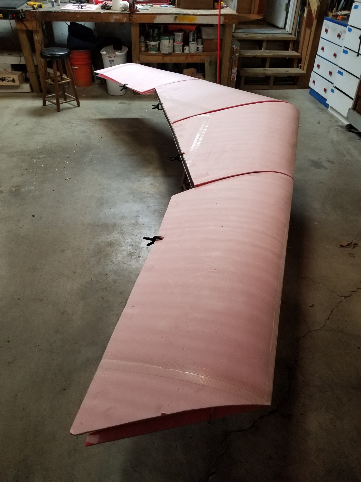
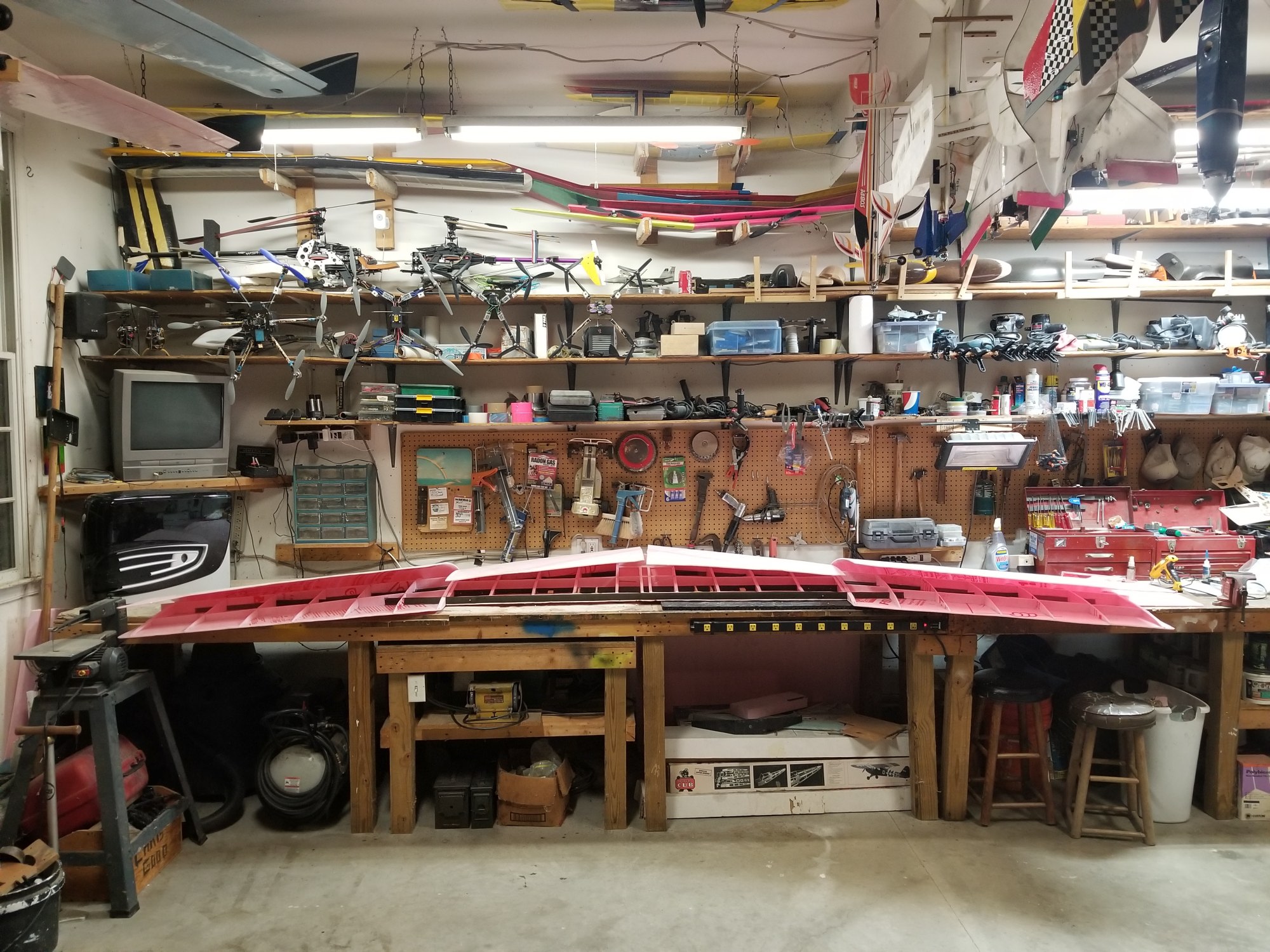
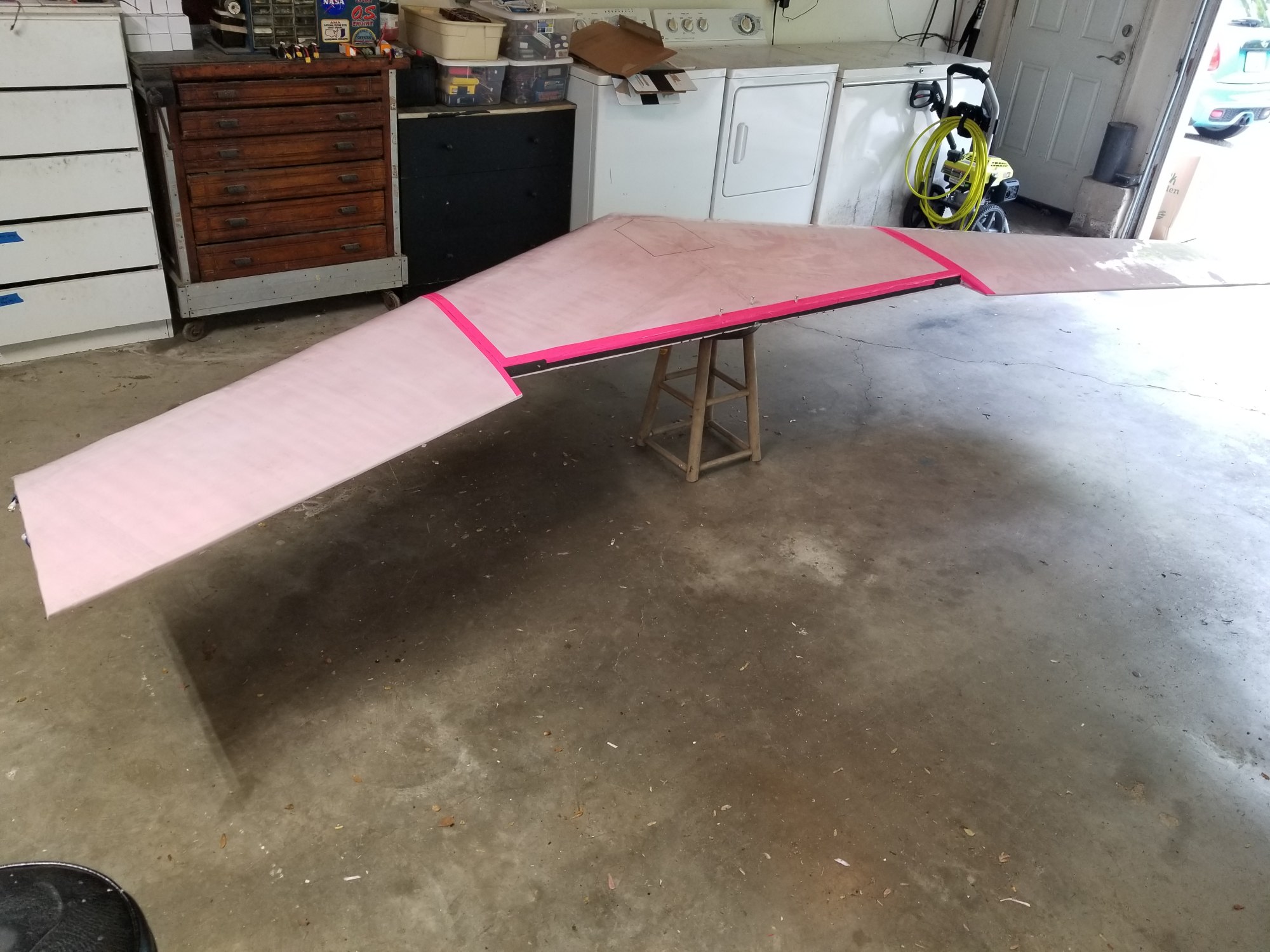
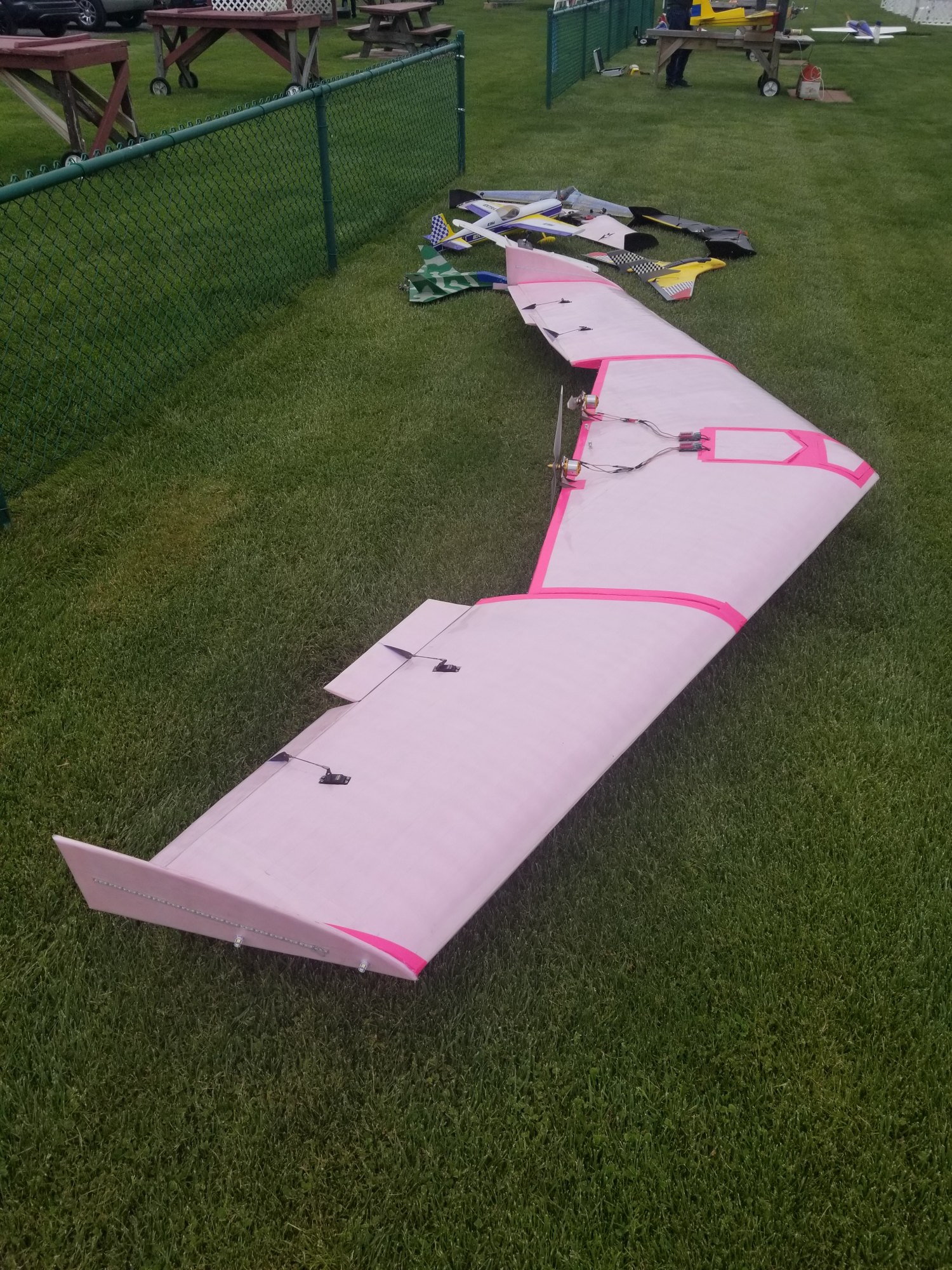
The top foam was folded over and glued in place, and then covering began. The entire surface is covered with 3" wide clear packing tape, and the seams are closed with pink duct tape. I then added the servos, engine mounts, and landing gear. The internal attachment points for the engine mounts and landing gear had been put in place before gluing the top foam.
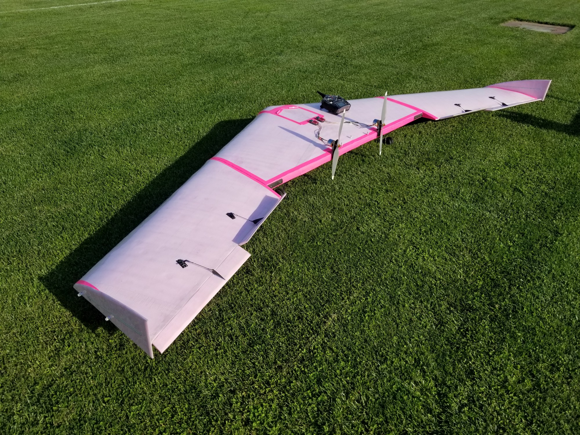
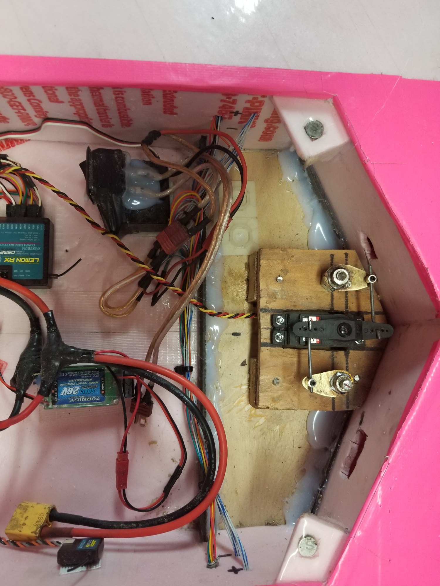
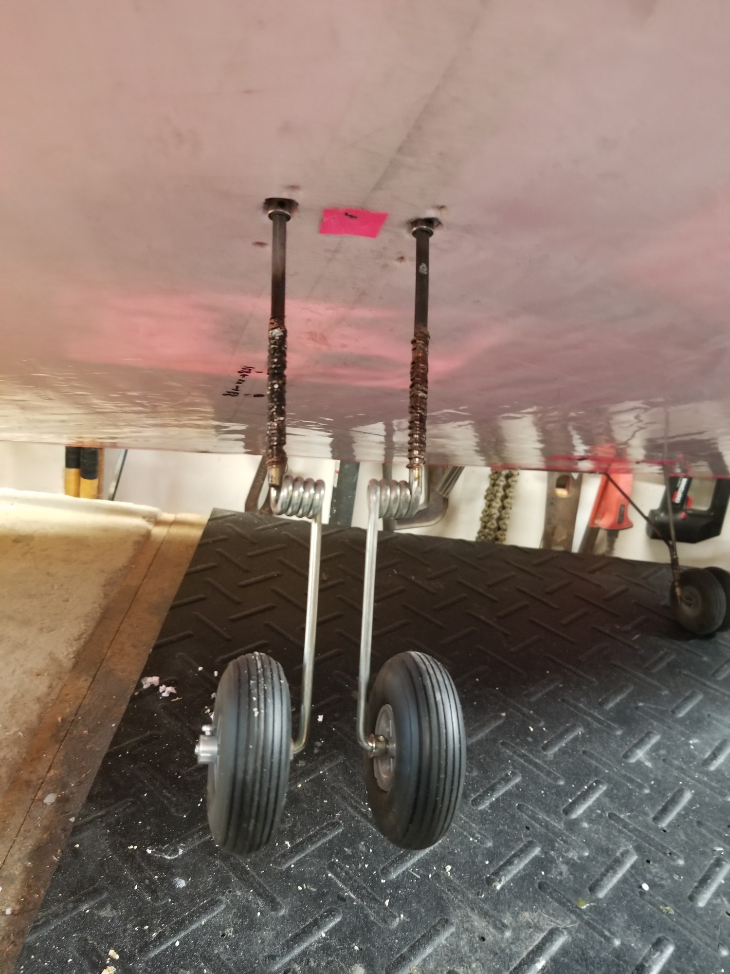
The center of gravity was set at the same % MAC as I have used on my 6' planes for many years. This proved to be way to far back, as the first flight attempt showed the CG was not correct and the wing was unstable in pitch. This flight attempt also showed that the landing gear needed to be beefed up, so I added second supports to the main gear and doubled the nose gear. These photos show the new double nose gear and servo steering connection in the main center bay.
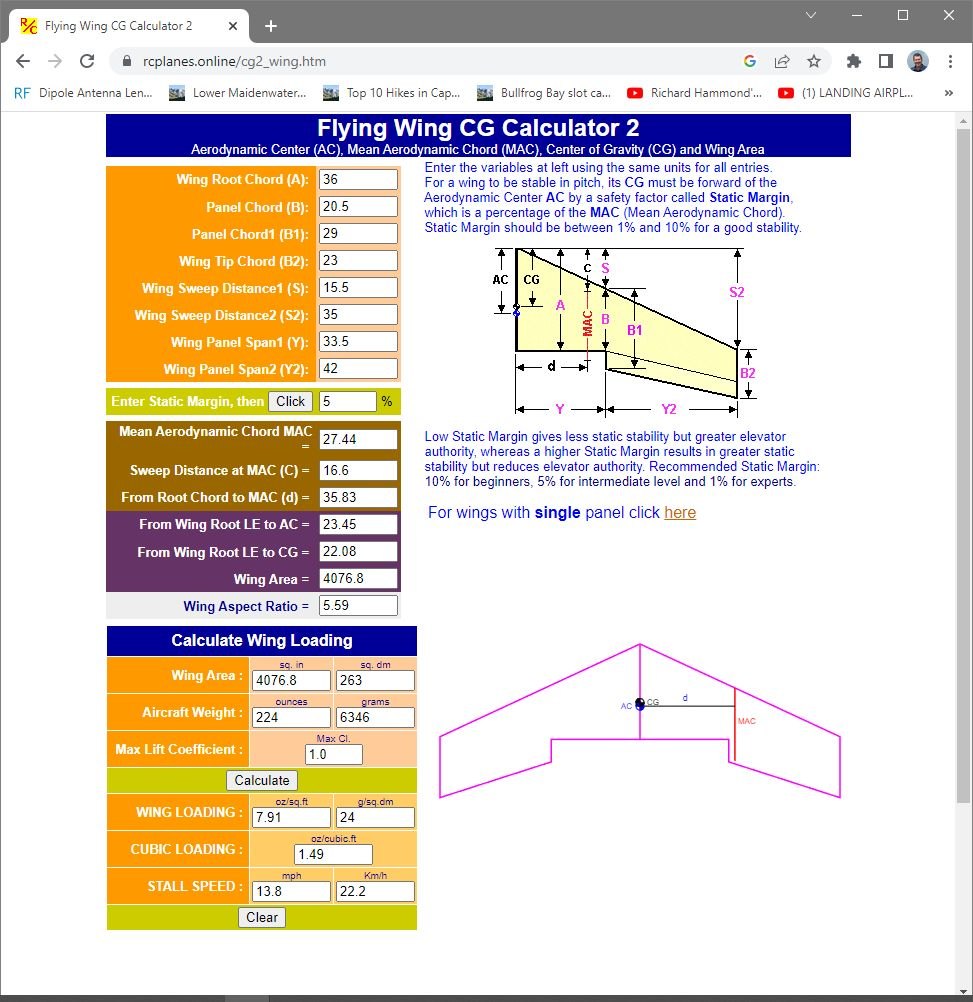
I re-calculated the CG using this web page, and added the appropriate weight to the nose section in the battery bay. The wing is now marked with a 5% to 15% static margin CG range. My next attempt at flight was at about 8% static margin according to these calculations. This proved to be very stable, as the first flight went well. The wing required quite a bit of back stick for level flight, but took off in a short distance and had almost no landing roll in 6 knot winds. I will be adjusting the CG after more flights as I become comfortable with the plane's flying.