Aiptek Pencam Trio II
An inexpensive pencam, this digital camera shoots 640x480 resolution and holds 26 pictures. I wired it up for a friend of mine using the same chip from Mr. RC-Cam. The sleep function really hinders this camera for AP, but I figured out where an active high AWAKE contact is, so the camera works fine using the WAKEUP function. Aiptek makes many different small digital cameras. The Mega Pencam and Pencam SD are ideally suited for aerial photography, but some of the others work just as well.
This project makes use of Mr. RC-Cam's PIC (programmable integrated circuit) and a bit of solder to allow you to close the shutter electronically from the ground via remote control. The full details of the project are at his page, but the specific connections for the Pencam Trio II are here. Before you attempt this project, read the full details at MR.RC-Cam's page first. The Trio II does not work using the USB power option. It was designed to only by controlled via the USB connection when plugged into the computer, so the batteries MUST be left in the camera to power it during flight and the + line from the RC receiver must only go to the PIC to power it, not to the USB connector also. Ground must be common between the PIC and camera, so that connection is made. It also enters "SLEEP" mode after 30 seconds of inactivity, so we must wire up the WAKEUP function from the PIC to enable pictures to be taken.
|
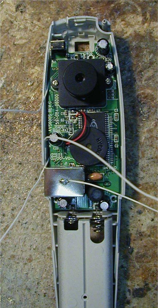
Here is what the Pencam Trio II looks like after removing the front cover (ignore the extra wires - the details on those are coming up). You will need to solder a total of 4 wires coming off the camera - GROUND(COMMON), AWAKE, WAKEUP, and SHUTTER. GROUND can be seen in this picture attached to the top of the USB casing. |
|
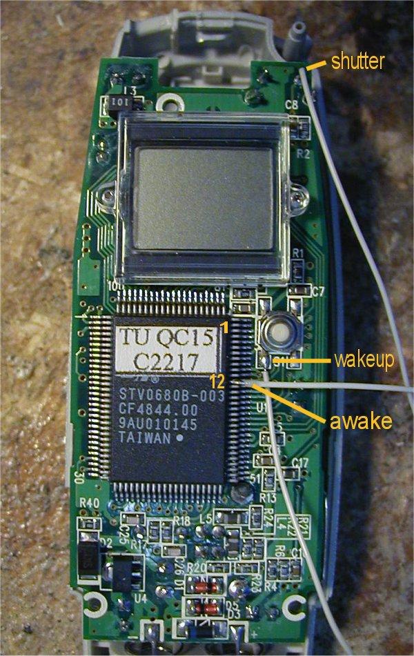
After removing three screws and flipping the main board over, this is what
you see. The shutter button at the top of the board closes the shutter by driving
the connection to ground. That is labeled SHUTTER. The connection labeled AWAKE goes high (+3.3 volts) when the camera is not in SLEEP mode. It is the 12th pin down on the right side of the main computer chip on the camera board. When the camera is in SLEEP mode, that pin is at +0 volts. The final connection is WAKEUP. When the camera is in SLEEP mode, is must be woken up. That is done via the WAKEUP pin, part of the mode button on the back of the camera when it is assembled. |
How does all this work? The PIC from MR.RC-Cam monitors the signal coming from your RC receiver. When that signal, known as a pulse width modulated (PWM) signal goes from low to high, the PIC begins its work. It checks the AWAKE signal coming from pin 12 as shown above. If the signal is low (+0 volts), it wakes up the camera by momentarily driving the WAKEUP line to ground. That wakes up the camera. It then drives the SHUTTER line momentarily to ground to electronically close the shutter. If the camera is already awake (AWAKE line high: +3.3 volts), it skips the wakeup portion and immediately drives the SHUTTER line to ground momentarily. Please read Mr.RC-Cam's CamMan project in detail before you do these modifications to your camera.
Back to the Aerial Photography Page